Eureka AIR delivers breakthrough ideas for toughest innovation challenges, trusted by R&D personnel around the world.

Low-voltage switch cabinet top plate

A low-voltage switchgear and roof technology, applied in the field of low-voltage switchgear, can solve the problems of deformation of the top cover, inconvenient maintenance, and difficulty in opening the top cover, and achieve the effects of preventing deformation, simple structure and convenient use.

Inactive Publication Date: 2019-03-05
UONONE GRP JIANGSU ELECTRICAL CO LTD
View PDF1 Cites 1 Cited by
  • Summary
  • Abstract
  • Description
  • Claims
  • Application Information

AI Technical Summary

Problems solved by technology

[0002] Low-voltage switchgear is suitable for power plants, petroleum, chemical industry, metallurgy, textiles, high-rise buildings and other industries. It is used for power transmission, power distribution and power conversion. In order to facilitate wiring, the low-voltage switchgear generally sets the busbar on the top of the switchgear. In one of the compartments, it is usually covered with a top cover plate. The structure of the traditional top cover plate wins a whole piece of steel plate, which makes it easy to cause deformation of the top cover plate when hoisting the low-voltage switchgear, thus affecting the quality of the entire low-voltage switchgear. At the same time, after the cabinet assembly is completed at the work site, it is difficult to open the top cover in the narrow power distribution room, resulting in the inability to insert and install the busbars, which brings great inconvenience to later maintenance. It is difficult to fix on the cabinet, and the protection of internal equipment is not in place

Method used


Image

  • Low-voltage switch cabinet top plate
  • Low-voltage switch cabinet top plate
  • Low-voltage switch cabinet top plate

Examples


Embodiment Construction

[0016] The following will clearly and completely describe the technical solutions in the embodiments of the present invention with reference to the accompanying drawings in the embodiments of the present invention. Obviously, the described embodiments are only some, not all, embodiments of the present invention.

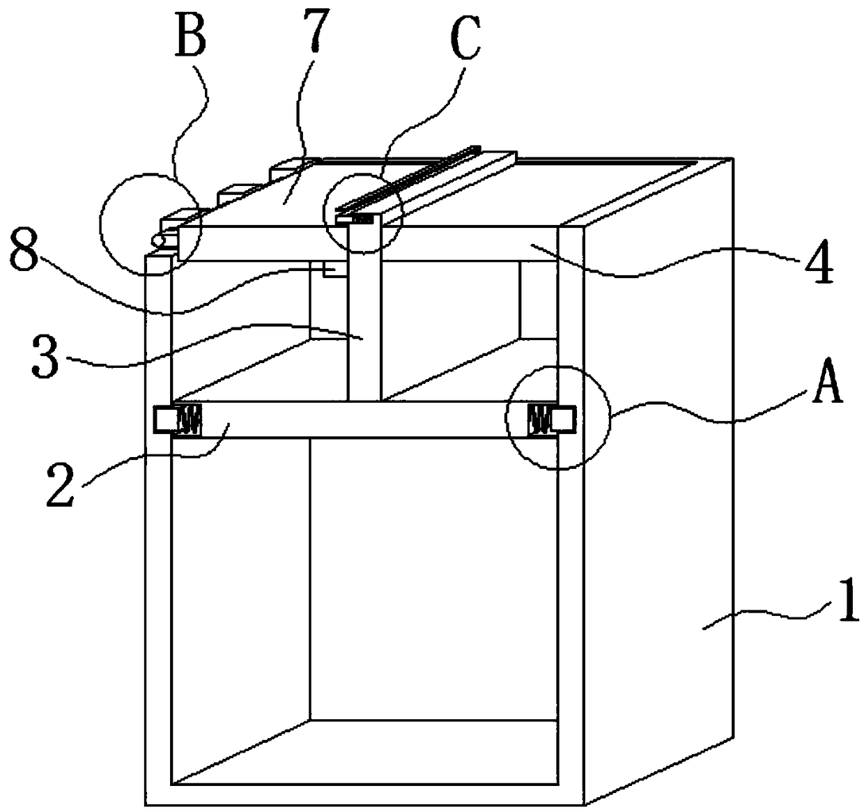
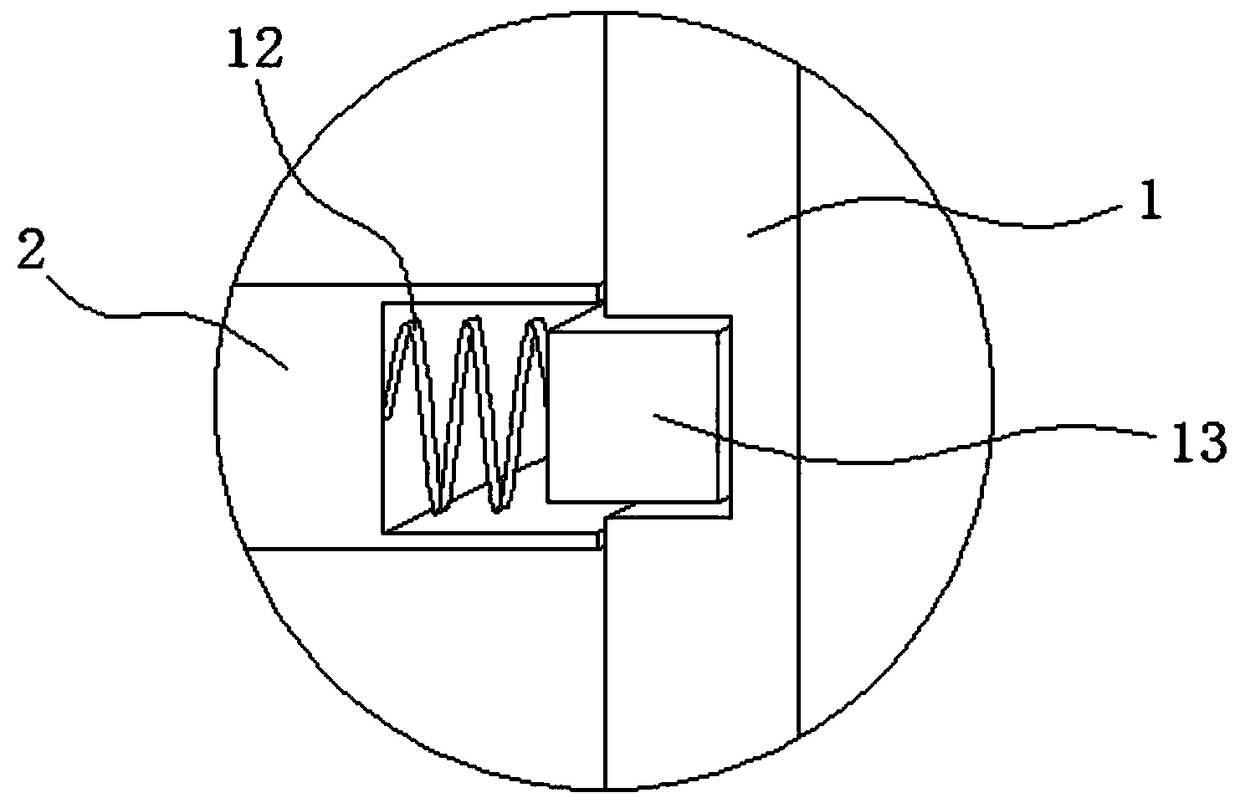
[0017] refer to Figure 1-4 , a low-voltage switchgear top plate, including a cabinet body 1, a horizontally arranged support plate 2 is provided in the cabinet body 1, and second installation grooves are symmetrically provided on both sides of the support plate 2, and the bottom of the second installation groove passes through the second round The elastic device 12 is connected with a second limiting block 13, and the inner side wall of the cabinet body 1 is provided with a limiting groove corresponding to the second limiting block 13, which facilitates the installation and removal of the support plate 2, thereby facilitating the installation and removal of the suppo...


PUM


Abstract

The invention discloses a low-voltage switch cabinet top plate, which comprises a cabinet body, wherein a horizontal supporting plate is arranged in the cabinet body; one side, which is far away fromthe inner bottom of the cabinet body, of the supporting plate is fixedly provided with a vertical stand column; one side of the stand column is fixedly provided with a first top cover plate; one side,which is far away from the stand column, of the first top cover plate is fixed on the inner side wall of the cabinet body; the upper end of one side, which is far away from the first top cover plate,of the cabinet body is provided with a notch; the side wall of the notch is rotatably connected with a spindle; the spindle is connected with a second top cover plate through a connecting block; andone side, which is near the second top cover plate, of the stand column is provided with a stop block and a first installation groove. The top plate has a simple structure and is convenient in use, the low-voltage switch cabinet can be prevented from deforming in a hoisting process through the supporting of the supporting plate, the top cover plate is divided into two parts so as to bring convenience in carrying out later-period maintenance on the internal equipment of the low-voltage switch cabinet in a narrow distribution room, and the top cover plate is convenient in fixing so as to be favorable for protecting internal equipment.

Description

technical field [0001] The invention relates to the technical field of low-voltage switch cabinets, in particular to a top plate of a low-voltage switch cabinet. Background technique [0002] Low-voltage switchgear is suitable for power plants, petroleum, chemical industry, metallurgy, textiles, high-rise buildings and other industries. It is used for power transmission, power distribution and power conversion. In order to facilitate wiring, the low-voltage switchgear generally sets the busbar on the top of the switchgear. In one of the compartments, it is usually covered with a top cover plate. The structure of the traditional top cover plate wins a whole piece of steel plate, which makes it easy to cause deformation of the top cover plate when hoisting the low-voltage switchgear, thus affecting the quality of the entire low-voltage switchgear. At the same time, after the cabinet assembly is completed at the work site, it is difficult to open the top cover in the narrow pow...

Claims


Application Information

Patent Timeline
Patent Type & Authority Applications(China)
IPC IPC(8): H02B1/30H02B1/28
Inventor 郭文祥孔祥超吴峰
Owner UONONE GRP JIANGSU ELECTRICAL CO LTD
Why Eureka
Eureka Blog
Learn More