Foundation pit temporary power system and construction method thereof

A technology for temporary power consumption and construction methods, applied in infrastructure engineering, excavation, cable installation, etc., can solve problems such as difficulty in ensuring the safety of power consumption at the construction site, achieve the effect of reducing random laying and dragging, and reducing potential safety hazards

Active Publication Date: 2019-03-05
CHINA MCC20 GRP CORP
View PDF5 Cites 0 Cited by
  • Summary
  • Abstract
  • Description
  • Claims
  • Application Information

AI Technical Summary

Problems solved by technology

[0004] Wires are laid and dragged randomly, which makes it difficu

Method used


Image

  • Foundation pit temporary power system and construction method thereof

Examples


Embodiment Construction

[0019] The present invention will be further described below in conjunction with the accompanying drawings and specific embodiments, so that those skilled in the art can better understand the present invention and implement it, but the examples given are not intended to limit the present invention.

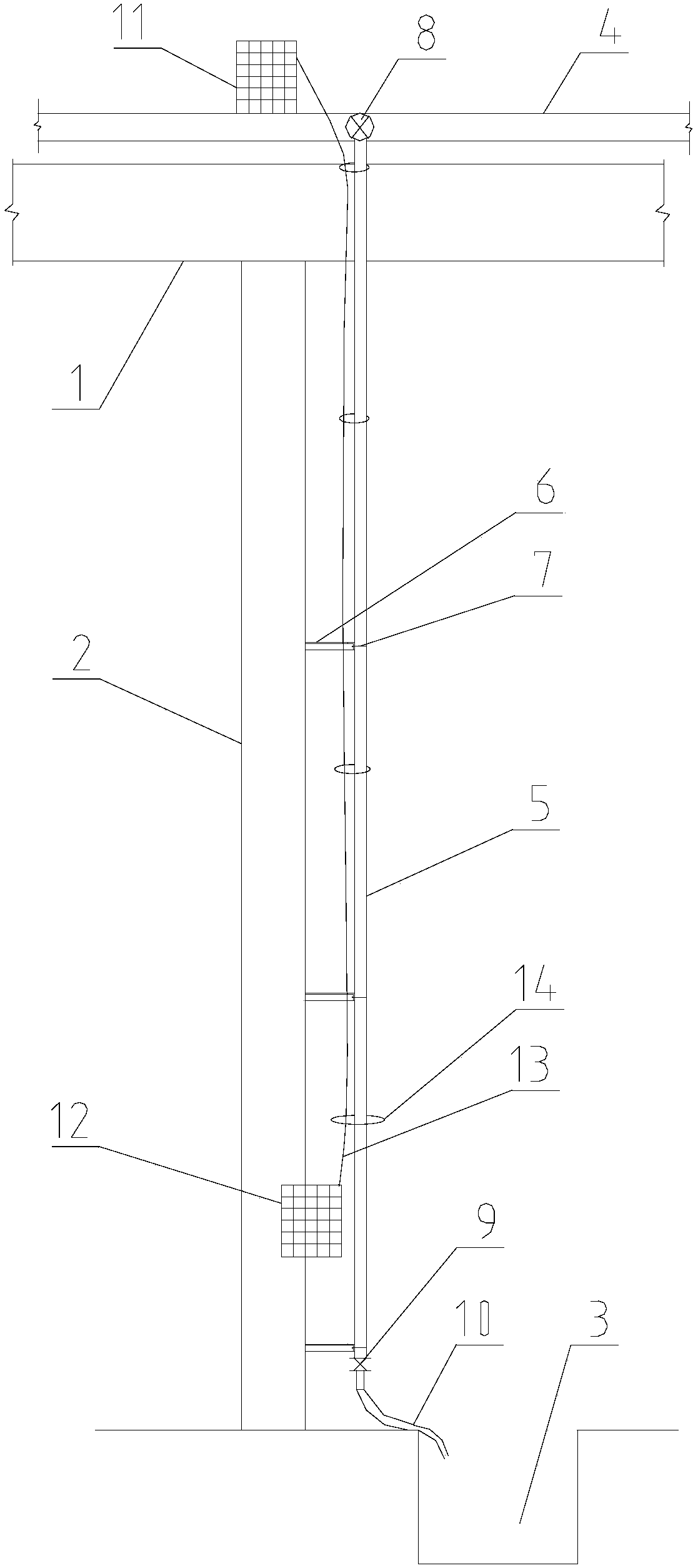
[0020] A foundation pit water supply and drainage system, comprising:

[0021] Horizontal pipe 4, the specification is DN100, and the material is galvanized welded steel pipe;

[0022] Standpipe 5: the specification is DN50, and the material is galvanized welded steel pipe;

[0023] Valve 9: check valve with specification DN50 and material made of cast iron;

[0024] Tube clamp 7: tube clamps with specifications of DN100 and DN50;

[0025] Bracket 6: Angle steel with a specification of 50mm;

[0026] Railings (not shown);

[0027] like figure 1 As shown, the lattice column 2 of the foundation pit is welded from top to bottom to fix a plurality of supports 6 , and the distance...


PUM


Abstract

The invention provides a foundation pit temporary power system and a construction method thereof, wherein the foundation pit temporary power system comprises at least one first level distribution boxand at least one second level distribution box, the first level distribution box is mounted at a connection part between a vertical tube and a horizontal tube in a foundation pit water supply and drainage system, one end of the first level distribution box is connected with a general distribution box and the other end thereof is connected with the second level distribution box, and the second level distribution box is mounted at the lower end of the vertical tube, 0.8-1.5m away from the bottom of the foundation pit; and a wire between the first level distribution box and the second level distribution box is bound and fixed on the vertical tube. According to the foundation pit temporary power system provided by the invention, based on the foundation pit water supply and drainage system in the foundation pit, the wire is bound and paved at the same time while the foundation pit water supply and drainage system is constructed, and the wire originally paved and arranged along a pit wall isdesigned to be a three-dimensional power supply system. A project temporary power system is optimized, and potential safety hazard is reduced.

Description

technical field [0001] The invention relates to the technical field of civil engineering construction, in particular to a foundation pit temporary power consumption system and a construction method thereof. Background technique [0002] During the construction of large-scale deep foundation pit projects, the temporary power system is affected by the structural characteristics of the project itself (the elevation of the pit bottom is low), which makes it difficult. It is usually designed to arrange a secondary power supply box along the periphery of the foundation pit wall, and then lay the wires into the interior of the foundation pit along the foundation pit wall. [0003] For example, the average longitudinal length of the foundation pit of a certain project is 70 meters. The deepest excavation of the foundation pit is 12.2 meters. The temporary power system is to arrange the general distribution box around the wall of the foundation pit, and then lay the wires into the ...

Claims


Application Information

Patent Timeline
IPC IPC(8): H02G9/06E02D17/02
CPCE02D17/02H02G9/06
Inventor 王争刘畅史卫东高国庆王丽丽马钦华
Owner CHINA MCC20 GRP CORP
Why Eureka
Try Eureka