Paper drawing machine with rebound type cutter structure

A technology of paper pumping machine and cutting knife, which can be applied to home appliances, etc. It can solve the problems of difficulty in changing paper rolls and inconvenient paper towels, and achieve the effects of convenient and quick replacement, reduced labor costs, and simple and reasonable structure

Pending Publication Date: 2019-03-08
杭州数策指今科技有限公司
View PDF0 Cites 0 Cited by
  • Summary
  • Abstract
  • Description
  • Claims
  • Application Information

AI Technical Summary

Problems solved by technology

[0004] The purpose of the present invention is: in order to solve the problem that the paper towels are inconvenient to pass through the gap between the rollers afte

Method used


Image

  • Paper drawing machine with rebound type cutter structure
  • Paper drawing machine with rebound type cutter structure
  • Paper drawing machine with rebound type cutter structure

Examples


Example Embodiment

[0044] Example 1

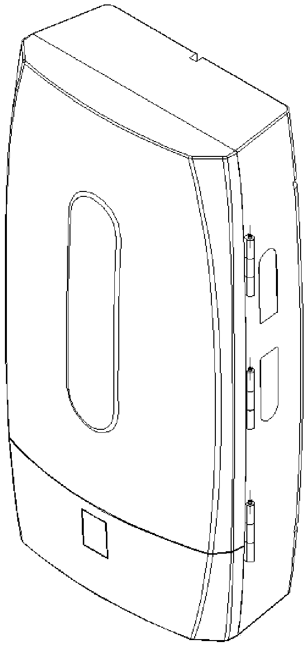
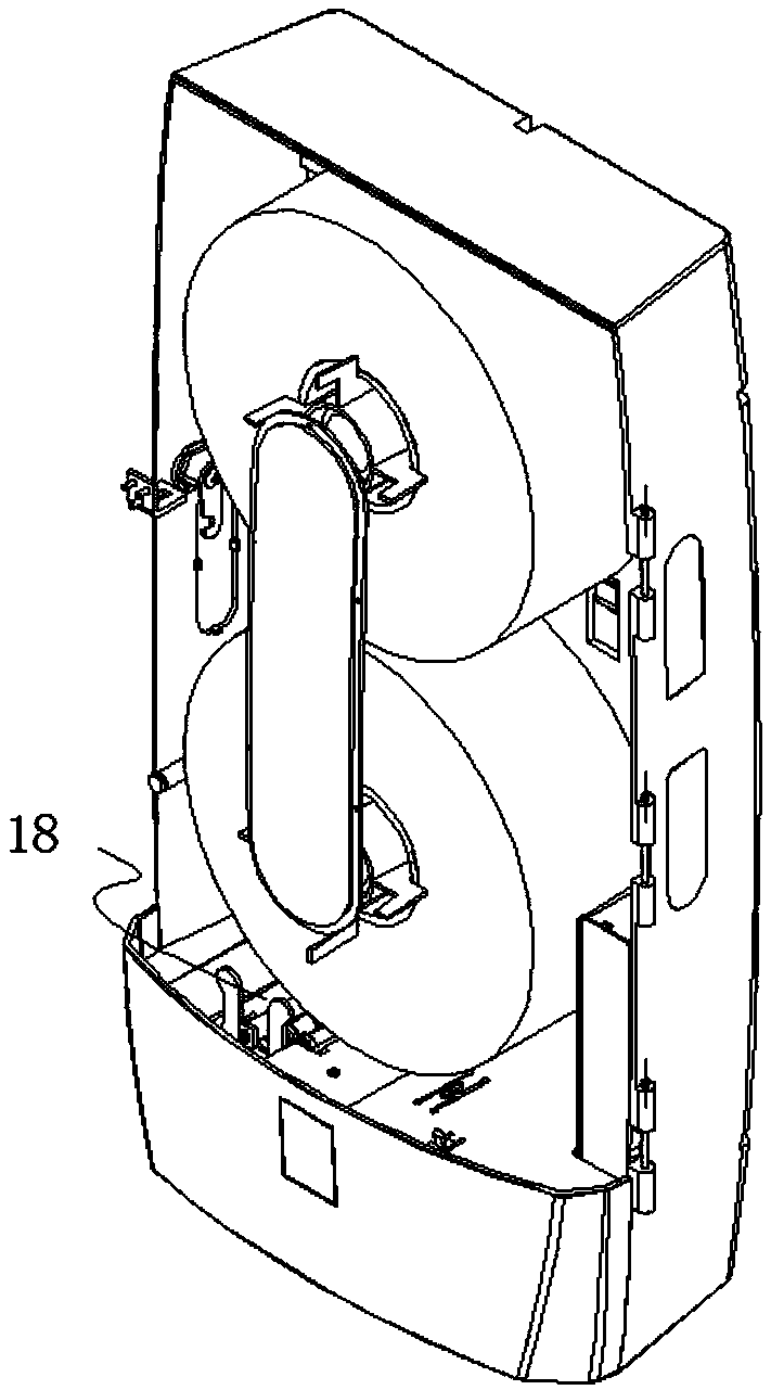
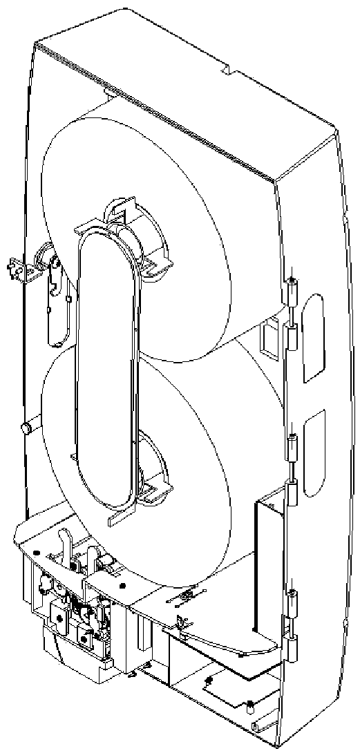
[0045] A paper pumping machine with a resilient cutter structure includes a body 10, a tissue chamber is arranged on the upper part of the body 10, and an organic core is arranged on the lower part of the body. The core includes a placing frame 1 fixed on the body 10 for placing Supporting plates 2 are provided on both sides of the upper end of the frame 1, and a first roller 310 and a third roller 320 located below the first roller 310 are provided between the two supporting plates 2. A first rotating plate 410 and a second rotating plate 420 are respectively provided on both sides. Both ends of the first rotating plate 410 and the second rotating plate 420 are bent downward to form a bending portion 5, and the bending portion 5 is connected to the placing frame. The outer wall of 1 is rotatably connected, the upper ends of the first rotating plate 410 and the second rotating plate 420 are respectively provided with a left supporting plate 210 and a right supp...

Example Embodiment

[0047] Example 2

[0048] On the basis of the first embodiment, one end of the first roller shaft 310 and the third roller shaft 320 passes through the supporting plate 2 and is respectively sleeved with a first gear 311 and a third gear 321, and one end of the second roller shaft 330 After passing through the left supporting plate 210, a second gear 331 meshing with the first gear 311 is sleeved. One end of the fourth roller shaft 340 passes through the right supporting plate 220 and sleeved with a fourth gear 321 meshing with the third gear 321. Gear 341.

[0049] In this embodiment, through gear meshing transmission, the first gear 311 meshes with the second gear 321, and the third gear 331 meshes with the fourth gear 341. When the driving device drives one gear to rotate, the two meshed gears rotate toward each other and drive The paper moves downward, and a paper output unit can convey the paper through a driving mechanism, and the structure is simple and reasonable.

Example Embodiment

[0050] Example 3

[0051] On the basis of embodiment 1, the other ends of the first roller shaft 310 and the third roller shaft 320 penetrate the supporting plate 2 and the left supporting plate 210 respectively, and then are connected with the first spring 710, the second roller shaft 320 and the fourth roller shaft 320. The other end of the roller shaft 340 penetrates the supporting plate 2 and the supporting plate 2 respectively, and is connected with a second spring 720.

[0052] In this embodiment, the first spring 710 and the second spring 720 respectively ensure that the first roller shaft 310 and the second roller shaft 320, and the third roller shaft 330 and the fourth roller shaft 340 are tightly connected, so that the passage After manually rotating the first rotating plate 410 and the second rotating plate 420, when the first rotating plate 410 and the second rotating plate 420 are restored, the first roller 310 and the second roller 320, the third roller 330 and the fo...


PUM


Abstract

The invention discloses a paper drawing machine with a rebound type cutter structure, which comprises a machine body, wherein the upper part of the machine body is provided with a paper towel chamber;the lower part of the machine body is provided with a machine core; the machine core comprises a placing frame fixed on the machine body; two sides of the upper end of the placing frame are providedwith supporting plates; a first roller shaft and a third roller shaft positioned below the first roller shaft are arranged between the two supporting plates; the left side and the right side of the supporting plates are respectively provided with a first rotating plate and a second rotating plate; both ends of the first rotating plate and the second rotating plate are bent downwards to form a bending part; the bending part is rotationally connected with the outer wall of the placing frame; the two sides of the upper ends of the first rotating plate and the second rotating plate are respectively provided with left supporting plates and right supporting plates; the left supporting plate, the supporting plate and the right supporting plate on the same side are arranged side by side; a secondroller shaft and a fourth roller shaft are respectively arranged between the left supporting plates and between the right supporting plates. The paper drawing machine aims to solve the problem that the paper towels are inconvenient to pass through gaps between rollers after the roll paper in a paper towel machine is replaced.

Description

technical field [0001] The invention belongs to the technical field of paper towel pumping devices, and in particular relates to an automatic paper towel machine. Background technique [0002] Paper towels are essential sanitary products for people to travel, but in real life, most people find that they forget to bring paper towels when they need to use paper towels. For this reason, paper towel machines are often used as a shared device in hotels, restaurants, scientific research Institutions, hospitals, public entertainment venues and public toilets, etc., to solve people's paper needs. [0003] The paper output of the existing paper towel machine is rotated in opposite directions through the double rollers, which drives the paper to move downward. After the roll paper is used, the roll paper needs to be replaced. , the paper is inconvenient to pass directly through the gap between the double rollers, making it difficult to replace the paper roll. Contents of the invent...

Claims


Application Information

Patent Timeline
IPC IPC(8): A47K10/36A47K10/38
CPCA47K10/3606A47K10/38
Inventor 雷存亮李蕊蕊
Owner 杭州数策指今科技有限公司
Why Eureka
Try Eureka