Weight reducing device

A technology of decelerating stepper motor and spring box, applied in the field of medical rehabilitation, can solve the problems of lack of a larger adjustable range, difficult to adjust the demand for more variable, motor noise response speed, etc., so as to increase the use continuity, Low cost, lightweight and easy to install

Pending Publication Date: 2019-03-08
GUANGXI UNIVERSITY OF TECHNOLOGY
View PDF0 Cites 0 Cited by
  • Summary
  • Abstract
  • Description
  • Claims
  • Application Information

AI Technical Summary

Problems solved by technology

[0002] In the field of medical rehabilitation for the gait movement training of the lower limbs of the human body, the weight reduction mechanism has played an important role in the rehabilitation process. The form of wire traction achieves the purpose of weight reduction. Such a design requires a more fixed site before it can be applied, occupies a large space, and is not stable on objects that need to be moved.
During the working process, the motor will also emit noise and the response speed cannot keep up, and the patient will not feel comfortable during the rehabilitation process.
Moreover, most weight loss mechanisms on the market only rely on the motor to pull the spring to elongate to achieve weight loss in the form of pre-tightening force, or pull the cable close to the motor to achieve weight loss in the form of traction for the patient, and there is no greater adjustable range Also, it is difficult to adjust for the demand of variable more
Moreover, the motor will rotate at a high speed during the working process. The danger brought by such a working environment cannot be underestimated, and safety issues are particularly important.

Method used


Image

  • Weight reducing device
  • Weight reducing device
  • Weight reducing device

Examples


Embodiment 1

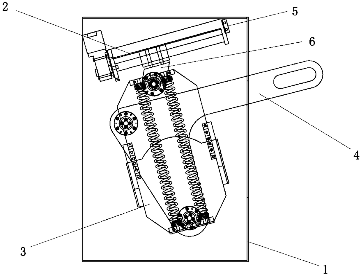
[0028] A weight reduction device design, as shown in 1 and 2, consists of a housing 1, a linear guide 2, a spring box 3, and a force arm 4.

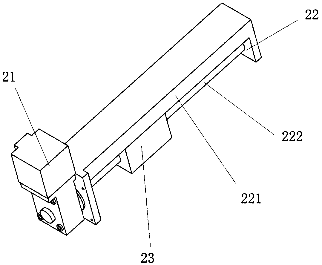
[0029] Such as image 3 As shown, the linear guide rail 2 is composed of a deceleration stepping motor 21, a screw slide 22, and a slider 23. The screw slide 22 is composed of a screw slide 221 and a screw 222. The slider 23 is mounted on the screw 222 and can move along the screw rod 222. The deceleration stepper motor 21 is installed on a side wall of the screw slide rail 221 by screws. The screw rod 222 passes through the side wall and is connected to the deceleration stepper motor 21. The deceleration stepper motor 21 Drive the screw 222 to rotate, and the screw 222 drives the slider 23 to move, combining figure 1 As shown, the other side wall of the screw slide rail 221 is connected to the housing 1 through the connecting plate 5. Specifically, the side wall is connected to the connecting plate 5 through screws, and the connecting plate...

Embodiment 2

[0033] The general structure is consistent with the embodiment, the difference is that the housing is made into a hollow design except where the force is concentrated.

[0034] The working principle of the weight reduction device design described in the above embodiment is: Image 6 Shown, F 1 For weight reduction, L 1 Is the length of the arm, F 2 Is the spring preload, L 2 Is the length of arm two, L 3 Is the spring arm, x is the adjustment stroke, L is the initial length of the spring, L′ is the total length of the spring after stretching, ΔL is the spring extension, and K is the spring stiffness coefficient. When designing the weight reduction device, specify the screw and vertical The straight direction is at an angle α, and the angle formed by the force arm one and the force arm two is also α, the angle between the spring and the force arm two is β, and the offset between the force arm fulcrum and the screw rod is a. It can be seen from the figure that the sliding block is ...


PUM


Abstract

The invention discloses a weight reducing device which is composed of a shell, a linear guide rail, a spring box and a force arm. The weight reducing device is compact in overall structure, an existing installing space can be effectively used, there is no need to reserve too much installation space for the weight reducing device during industrial design, and the workloads of the whole design process are reduced.

Description

Technical field [0001] The invention belongs to the field of medical rehabilitation, and specifically relates to a weight reduction device design. Background technique [0002] In the field of medical rehabilitation for human lower limb gait exercise training, weight reduction mechanisms have played an important role in the rehabilitation process. At present, most weight reduction mechanisms on the market use motors, pulleys, and springs as main parts, and then use steel cables to wind The form of wire traction achieves the purpose of weight reduction. Such a design requires a more fixed site to be applied, occupies a larger space, and is not stable on objects that need to be moved. During the work process, the motor will make noise and the response speed cannot keep up, and the patient feels poor comfort during the rehabilitation process. Moreover, most of the weight reduction mechanisms on the market only rely on the motor to pull the spring to achieve weight reduction in the ...

Claims


Application Information

Patent Timeline
Patent Type & Authority Applications(China)
IPC IPC(8): A61H3/00
CPCA61H3/008A61H2201/1207
Inventor 李健苗明达刘欢王荣耀吴青鸿
Owner GUANGXI UNIVERSITY OF TECHNOLOGY
Why Eureka
Try Eureka