Pneumatic fire extinguishing gun system

A fire extinguishing cannon, pneumatic technology, applied in the field of fire extinguishing cannon system, can solve the problems of potential safety hazards of pyrotechnic products, large size, short range, etc., and achieve the effects of avoiding potential safety hazards, high aiming accuracy, and controllable costs

Pending Publication Date: 2019-03-08
JIANGSU HOSEKING FIRE DEV CO LTD
View PDF7 Cites 8 Cited by
  • Summary
  • Abstract
  • Description
  • Claims
  • Application Information

AI Technical Summary

Problems solved by technology

Typical ones include SLM-60 individual shoulder-resistant fire extinguisher, SLM-105 bracket type fire extinguisher, CMH-1 long-distance intelligent forest fire extinguishing artillery system, etc., but the existing fire extinguishers are mainly driven by gunpowder gas Launching projectiles or using rocket engines as the power source for launching, the explosives involved in them have certain safety hazards in storage, transportation, and use, and their use in the civilian field faces strict restrictions on policies and standards, making it difficult to popularize and apply
CN 200510012974.2 discloses a bracket-type pneumatic fire extinguisher, but its shooting range is short (only 210m), and the height and orientation of the bracket are adjusted manually, which is inconvenient to use
CN201510538150.2 proposes a mechanical continuous pneumatic fire extinguisher, but the structure is complex, the volume is huge, and the influence of recoil is not fully considered

Method used


Image

  • Pneumatic fire extinguishing gun system
  • Pneumatic fire extinguishing gun system
  • Pneumatic fire extinguishing gun system

Examples


Embodiment Construction

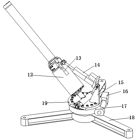
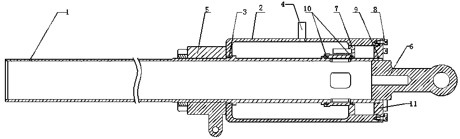
[0014] Such as Figure 1-3 As shown, a pneumatic fire extinguishing cannon system includes an air cannon 12, an electric cylinder 14, a support plate 15, a recoil device 18, a base 19, and an electrical control circuit. The base 19 is fixed on the recoil device 18 through a rotary support 17. The base 19 is provided with a motor 16, and the base 19 is fixed with an air cannon 12 through a support plate 15 and an electric cylinder 14. The air cannon 12 is provided with a sight 13, and the air cannon 12 includes a gun barrel 1, an air chamber 2, and a front trunnion 5 , the rear trunnion 6, the rear end of the gun barrel 1 runs through the air chamber 2 and is fixed with the air chamber, and the end is provided with a rear trunnion 6, the rear end of the air chamber 2 is fixed with an end cover 11, and the front end and the gun barrel 1 are connected. The sealing ring I3, the barrel 1 at the front end of the air chamber 2 is provided with a front trunnion 5, the end of the barre...


PUM


Abstract

The invention discloses a pneumatic fire extinguishing gun system. The pneumatic fire extinguishing gun system comprises an air gun, an electric cylinder, a support plate, a recoil device and a base;the base is movably fixed onto the recoil device through a rotary support; the base is provided with a motor; the air gun is fixed onto the base through the support plate and the electric cylinder; the air gun is provided with a gun sight; the air gun comprises a gun barrel, an air chamber, a front trunnion and a rear trunnion; the rear end of the gun barrel penetrates through the air chamber andis fixed to the air chamber, and the end part of the gun barrel is provided with the rear trunnion; the rear end of the air chamber is fixedly provided with an end cap; a seal ring I is arranged at the joint of the front end of the air chamber and the gun barrel; the gun barrel at the front end of the air chamber is provided with the front trunnion; a seal ring III is arranged between the end capand the gun barrel; and a piston is arranged in the air chamber. According to the pneumatic fire extinguishing gun system disclosed by the invention, by employing a pneumatic launching means, the potential safety hazard of an initiating explosive device is avoided; the air gun is compact in structure, simple in air channel, controllable in cost and high in reliability; and height and azimuth adjustment is performed by employing the electric cylinder and the motor, and the gun sight is equipped, so that the fire extinguishing gun is very high in sight precision.

Description

technical field [0001] The invention relates to a fire extinguishing cannon system, in particular to a pneumatic fire extinguishing cannon system. Background technique [0002] Fire extinguishing cannon is a new type of fire extinguishing equipment that has emerged in recent years. It can deliver fire extinguishing bombs to the fire scene from a long distance to avoid personal safety problems caused by close-range operations. Typical ones include SLM-60 individual shoulder-resistant fire extinguisher, SLM-105 bracket type fire extinguisher, CMH-1 long-distance intelligent forest fire extinguishing artillery system, etc., but the existing fire extinguishers are mainly driven by gunpowder gas Launching projectiles or using rocket engines as the power source for launch involves certain safety hazards in the storage, transportation, and use of the explosives involved, and the use in the civilian field faces strict restrictions on policies and standards, making it difficult to po...

Claims


Application Information

Patent Timeline
Patent Type & Authority Applications(China)
IPC IPC(8): A62C31/00A62C19/00
CPCA62C19/00A62C31/00
Inventor 钱国祥王晓伟邱卫阮海军朱克非
Owner JIANGSU HOSEKING FIRE DEV CO LTD
Why Eureka
Try Eureka