Medical care patient rehabilitation auxiliary device

An auxiliary device and patient technology, which is applied to elastic resistance devices, sports accessories, gymnastics equipment, etc., can solve the problems of single function, poor practicability, poor rehabilitation training effect, etc., and achieves convenient adjustment, flexible use, and convenient holding. Effect

Inactive Publication Date: 2019-03-08
苏莉娜
View PDF7 Cites 8 Cited by
  • Summary
  • Abstract
  • Description
  • Claims
  • Application Information

AI Technical Summary

Problems solved by technology

[0003] Rehabilitation auxiliary devices are often used in rehabilitation treatment. General medical care patient rehabilitation auxiliary devices have a single function, simple structure, flexible use, and cannot adjust the position of the handle ring, and the height of the seat board is inconvenient to adjust, and the effect of rehabilitation training is poor. , in actual use, the practicability is not strong

Method used


Image

  • Medical care patient rehabilitation auxiliary device
  • Medical care patient rehabilitation auxiliary device
  • Medical care patient rehabilitation auxiliary device

Examples


Embodiment 1

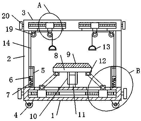
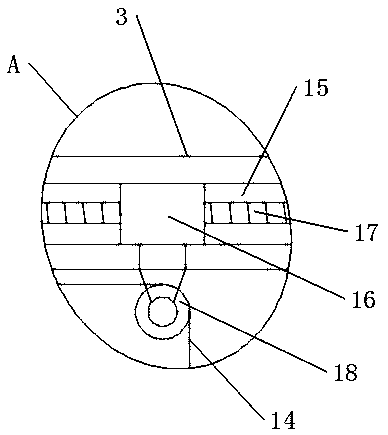
[0022] see figure 1 and image 3 , in an embodiment of the present invention, a medical care patient rehabilitation assisting device, including a base 1, a support column 2, a support beam 3, a support slider 6, a support spring 7, a seat board 8, a handle ring 13 and a pull cord 14, The upper surface of the end of the base 1 is fixedly equipped with a vertically arranged support column 2, and the horizontal support beam 3 is fixedly installed on the top of the support column 2, and the lower surfaces of both sides of the support beam 3 are arranged symmetrically. For the moving guide wheels 18 and the fixed guide wheels 19 that guide the stay cord 14, the upper surfaces of both sides of the base 1 are symmetrically fixed with support guide rails 5, and the support sliders 6 slide up and down and are arranged in the support guide rails 5. , the hand pull ring 13 is fixedly installed on one end of the stay rope 14, and the other end of the stay rope 14 is respectively wound ar...

Embodiment 2

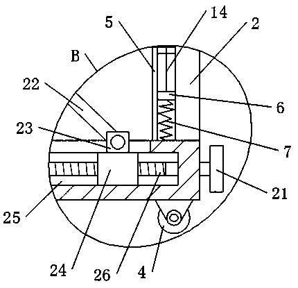
[0027] Unlike Example 1, see figure 1 and figure 2 , in the embodiment of the present invention, the seat board 8 is erected and installed on the base 1 through a lifting mechanism, and the lifting mechanism includes a supporting sleeve 10, a supporting sliding rod 11, a supporting connecting rod 22, a second moving slider 24 and a second moving slider 24. Two screw mandrels 26, the inside of the base 1 is provided with a second rectangular sliding cavity 25, the second screw mandrel 26 is rotated and installed in the second rectangular sliding cavity 25, and the horizontal sliding is arranged on both sides of the second rectangular sliding cavity 25 The second moving slider 24 is respectively installed on the outer circumferences on both sides of the second screw mandrel 26 through threaded connection, and further, the external threads on the outer circumferences on both sides of the second screw mandrel 26 have opposite directions of rotation; The lower surfaces of both en...


PUM


Abstract

The invention discloses a medical care patient rehabilitation auxiliary device. The device comprises a base, support columns, a support beam, support sliding blocks, support springs, a seat plate, hand rings and stay cords; moving guide pulleys and fixed guide pulleys which play a guide role for the stay cords are symmetrically arranged on the lower surfaces of the two sides of the support beam respectively, support guide rails are symmetrically fixedly arranged on the upper surfaces of the two sides of the base, the support sliding blocks sliding vertically are arranged in the support guide rails, the hand rings are fixedly installed at one ends of the stay cords, the other ends of the stay cords wind around the moving guide pulleys and the fixed guide pulleys to be connected with the support sliding blocks respectively, and the lower surfaces of the support sliding blocks are connected with the upper surface of the base through the support springs. Accordingly, the relative positionsof the two hand rings are adjusted according to different use requirements conveniently, a patient can hold the hand rings conveniently, and use is flexible; the height of the seat plate can be adjusted, and the device adapts to the use requirements of patients of different body types.

Description

technical field [0001] The invention relates to the technical field of medical rehabilitation equipment, in particular to a rehabilitation auxiliary device for medical care patients. Background technique [0002] In hospitals, some patients are often seen undergoing rehabilitation training. At present, physical rehabilitation training is a necessary measure to promote the rehabilitation of medical care patients. When the patient's condition begins to improve, assist the patient to carry out active limb training exercises, promote the recovery of autonomic nervous function, improve local blood circulation and nutritional status, effectively prevent the occurrence of complications, and enable the patient to recover better. [0003] Rehabilitation auxiliary devices are often used in rehabilitation treatment. General medical care patient rehabilitation auxiliary devices have a single function, simple structure, flexible use, and cannot adjust the position of the handle ring, an...

Claims


Application Information

Patent Timeline
Patent Type & Authority Applications(China)
IPC IPC(8): A63B23/12A63B21/02
CPCA63B21/02A63B23/12A63B2225/09A63B2225/093
Inventor 苏莉娜孙心平李翠萍
Owner 苏莉娜
Why Eureka
Try Eureka