Three-axis visual auto-screwdriving machine

An automatic locking screw machine, visual technology, applied in metal processing equipment, metal processing, manufacturing tools and other directions, can solve problems affecting product processing quality, destroying screw hole positions, inaccurate positioning, etc., to increase the quality of locking screws, guaranteeing Precise positioning and high reliability

Pending Publication Date: 2019-03-08
东莞市渝达自动化设备有限公司
View PDF6 Cites 11 Cited by
  • Summary
  • Abstract
  • Description
  • Claims
  • Application Information

AI Technical Summary

Problems solved by technology

[0003] However, the current automatic screw locking machine often has inaccurate positioning when locking screws, making the screws on the screw holes unable to be tightened effectively, or destroying the original screw holes, which seriously affects the later product processing. Quality, therefore, needs to be improved

Method used


Image

  • Three-axis visual auto-screwdriving machine
  • Three-axis visual auto-screwdriving machine
  • Three-axis visual auto-screwdriving machine

Examples


Embodiment 1

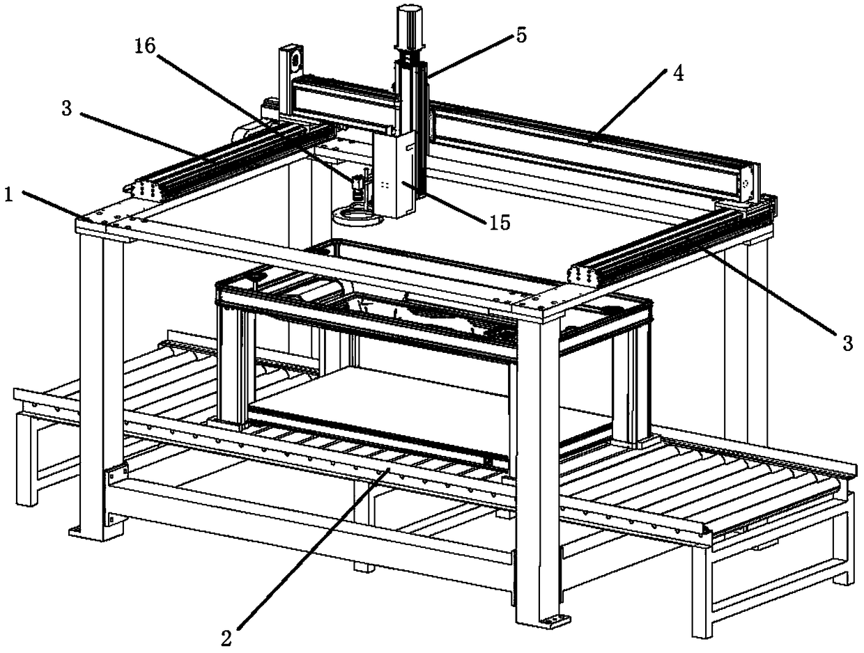
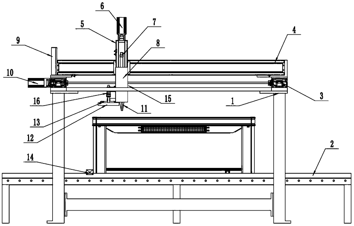
[0024] refer to Figure 1~3 , in an embodiment of the present invention, a three-axis visual automatic screw locking machine includes a load-bearing frame 1, the weighing frame 1 belongs to a steel structure, which can prevent the module from shaking during operation, and the middle of the lower end of the load-bearing frame 1 is provided with The positioning roller conveying line 2, the workpiece to be processed is placed on the positioning roller conveying line 2, the Y-axis module 3 is installed on the left and right sides of the upper end of the load-bearing frame 1, and the Y-axis module 3 moves stably and at a fast speed. An X-axis module 4 is installed between the middle parts of the axis modules 3, and the movement of the Y-axis module 3 is also stable and fast. The X-axis module 4 includes an X-axis servo motor 10 and a speed-changing synchronous wheel 9, X A Z-axis module 5 is installed in the middle of the axis module 4. The Z-axis module 5 includes a Z-axis motor 6...

Embodiment 2

[0026] In another embodiment of the present invention, the difference between this embodiment and the above-mentioned embodiment is that a positioning blocking cylinder 14 is installed on the upper end of the positioning roller conveying line 2, and the positioning blocking cylinder 14 can effectively move the to-be-processed The workpiece is limited on the positioning roller conveying line 2, thereby effectively avoiding shaking when the workpiece is tightened.

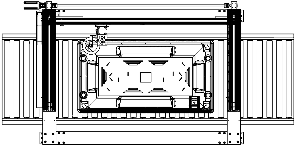
[0027] In the present invention, when in use, the workpiece product is conveyed through the positioning roller conveying line, and then the visual device is used to guide the cooperation between the X-axis module, the Y-axis module and the Z-axis module, so that the nail feeding mechanism 15 drives the cross The batch head 11 is rotated to tighten the screw in the product, ensuring machining accuracy, simple operation and strong practicability.


PUM


Abstract

The invention discloses a three-axis visual auto-screwdriving machine, and belongs to the technical field of auto-screwdriving machine equipment. The three-axis visual auto-screwdriving machine comprises a load-bearing frame, a positioning roller conveying line is arranged on the middle part of the lower end of the load-bearing frame, workpieces to be processed are arranged on the positioning roller conveying line, Y-axis modules are installed on the left and right sides of the upper end of the load-bearing frame, X-axis modules are installed on the middle parts of the Y-axis modules, Z-axis modules are installed on the middle parts of the X-axis modules, and a nail sending mechanism and a visual device are correspondingly installed at the bottom ends of the Z-axis modules. The three-axisvisual auto-screwdriving machine has reasonable structure and novel design, through the mutual cooperation among the X-axis modules, the Y-axis modules and the Z-axis modules, the three-dimensional movement of the nail sending mechanism is realized, at the same time, the visual device is used to further ensure the accurate positioning of the nail sending mechanism, the quality of screwdriving of the workpieces to be processed is greatly improved, practicality is high, and reliability is high.

Description

technical field [0001] The invention relates to the technical field of automatic screw locking machine equipment, in particular to a three-axis visual automatic screw locking machine. Background technique [0002] The automatic locking screw machine realizes the automatic conveying, tightening and testing of screws through various electric and pneumatic components, and simplifies the screw fastening process through equipment, so as to reduce the number of labor and reduce the adverse factors caused by manual misoperation. It is a typical non-standard automation equipment. The automatic locking screw machine is mainly divided into: hand-held locking screw machine, multi-axis automatic locking screw machine, coordinate automatic locking screw machine. [0003] However, the current automatic screw locking machine often has inaccurate positioning when locking screws, making the screws on the screw holes unable to be tightened effectively, or destroying the original screw holes,...

Claims


Application Information

Patent Timeline
Patent Type & Authority Applications(China)
IPC IPC(8): B23P19/06
CPCB23P19/06
Inventor 许曾明周祁阳
Owner 东莞市渝达自动化设备有限公司
Why Eureka
Try Eureka