Automatic feeding equipment

A technology of equipment and materials, applied in the field of automatic feeding equipment, can solve problems such as easy confusion, increased labor intensity of workers, safety accidents, etc.

Pending Publication Date: 2019-03-08
FOSHAN NANHAI GUANGDONG TECH UNIV CNC EQUIP COOP INNOVATION INST +1
View PDF0 Cites 4 Cited by
  • Summary
  • Abstract
  • Description
  • Claims
  • Application Information

AI Technical Summary

Problems solved by technology

Due to the sequence and direction requirements of the series connection of materials, it is easy to be confused during manual operation. Due to the large production volume, the labor intensity of workers will also be increased. In addition, when loading materials, they must be placed in the processing equipment, which is prone to safety accidents. Therefore, the prior art needs to be further improved and perfected

Method used


Image

  • Automatic feeding equipment
  • Automatic feeding equipment
  • Automatic feeding equipment

Examples


Embodiment 1

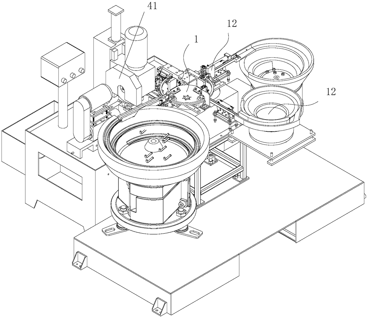
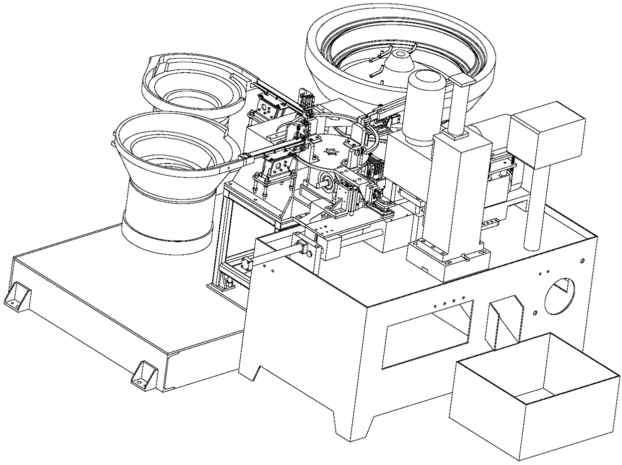
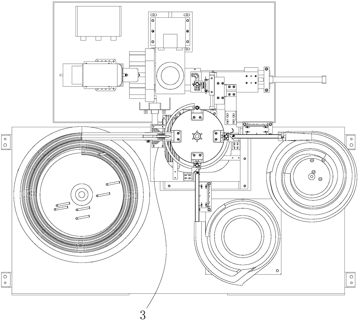
[0076] Such as Figure 1 to Figure 3 , Figure 20 As shown, this embodiment discloses an automatic feeding device, which mainly includes a feeding frame 13, a driving device 1 mounted on the feeding frame 13 for driving material rotation, placing the first and second The positioning and discharging device 12 for the second material, the positioning and turning device 3 for placing the third material, and the clamping and feeding device 43 for clamping the serially connected materials. The loading frame 13 is arranged on the front side of the processing equipment 41 . The driving device 1 is installed in the middle of the feeding frame 13, and adopts a four-station rotation design. The positioning and discharging device 12 is set as two groups. Two groups of the positioning and discharging device 12, the positioning and turning device 3, and the clamping and feeding device 43 are arranged around the driving device 1 at equal intervals in the circumferential direction. The d...


PUM


Abstract

The invention discloses automatic feeding equipment. The equipment comprises a feeding rack, a driving device, positioning and placing devices, a positioning and turning device, and a clamping and conveying device. During feeding, the positioning and placing device located at the first station places a first hexagon nut in a tool clamp in an opening facing downwards mode; then a rotary disc is driven to turn to the next station, the positioning and placing device located at the second station places a second hexagon nut in the tool clamp in the opening facing downwards mode to enable the second hexagon nut to be stacked on the first hexagon nut; then the rotary disc is driven to turn to the next station, the positioning and turning device located at the third station conveys a bent pipe onto a lifting plate, and the lifting plate is driven by a material turning air cylinder to upwards turn over to enable the bent pipe to penetrate into the two hexagonal nuts in the tool clamp along a curve; and finally the rotary disc is driven to turn to the next station, the clamping and conveying device located at the fourth station integrally clamps materials which are connected in series, places the materials into a conveying plate for temporary storage, and conveys the materials one by one to machining stations for machining through conveying hydraulic cylinders.

Description

technical field [0001] The invention relates to the field of automatic manufacturing, in particular to an automatic feeding device for producing electric water heater reversing valve pipe fittings. Background technique [0002] At present, the material loading operation in the production of electric water heater reversing valve pipe fittings is manual. The three materials (two nuts with opposite directions and a bent pipe) are connected in series in sequence and direction, and then placed in series. Go to the processing station of the processing equipment for the next step of processing. Due to the sequence and direction requirements of the series connection of materials, it is easy to be confused during manual operation. Due to the large production volume, the labor intensity of workers will also be increased. In addition, when loading materials, they must be placed in the processing equipment, which is prone to safety accidents. Therefore, the prior art needs to be furthe...

Claims


Application Information

Patent Timeline
IPC IPC(8): B23P21/00
CPCB23P19/001B23P19/004B23P19/007B23P21/006
Inventor 郭子龙孙传碑
Owner FOSHAN NANHAI GUANGDONG TECH UNIV CNC EQUIP COOP INNOVATION INST
Why Eureka
Try Eureka