New energy vehicle charging device

A technology of new energy vehicles and charging equipment, which is applied in the direction of electric vehicle charging technology, charging stations, electric vehicles, etc., and can solve problems such as safety accidents, poor stability of charging cable plugging, easy loosening, etc.

Inactive Publication Date: 2019-03-08
张然
View PDF9 Cites 4 Cited by
  • Summary
  • Abstract
  • Description
  • Claims
  • Application Information

AI Technical Summary

Problems solved by technology

[0003] However, in the existing technology, the plugging stability of the charging line is poor, it is easy to loosen, it is easy to cause poor contact, and it is more likely to cause a safety accident caused by the falling off of the charging line. Therefore, when designing the existing charging pile, m

Method used


Image

  • New energy vehicle charging device
  • New energy vehicle charging device
  • New energy vehicle charging device

Examples


Embodiment 1

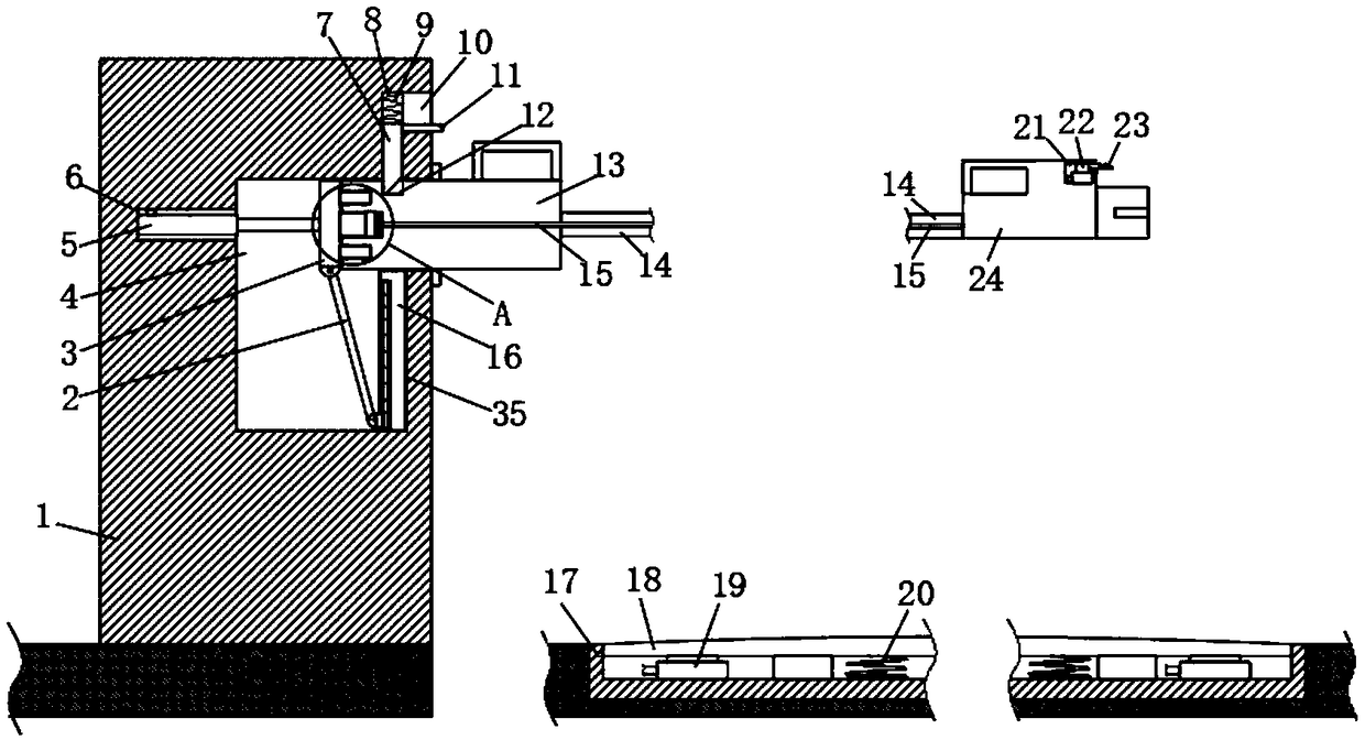
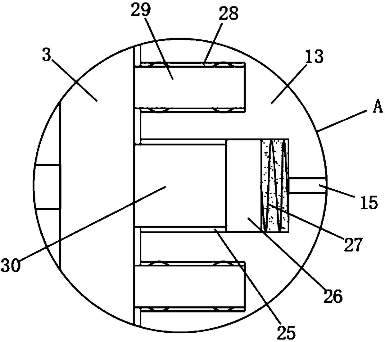
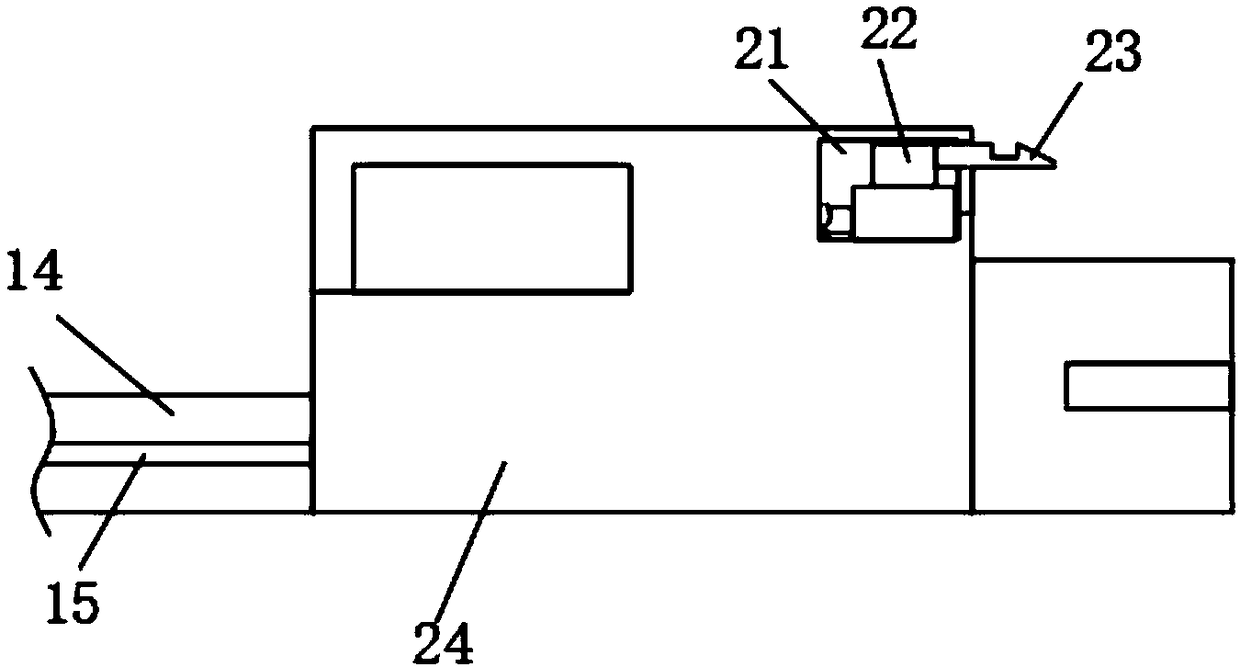
[0026] refer to Figure 1-4 , a new energy vehicle charging device, including a pile body 1, a charging line and an installation frame 17 installed under the ground of the parking space, the charging line includes a first plug 13, a second plug 24, and the first plug 13 and the second plug 24 pass through The connecting line 14 is connected, the inside of the pile body 1 is provided with a first installation groove 4, the inner wall of the first installation groove 4 is provided with a second installation groove 6, and the inner wall of the second installation groove 6 is fixedly connected with the first piston cylinder 5 , the installation frame 17 is provided with a control mechanism for controlling the action of the first piston cylinder 5, the telescopic end of the first piston cylinder 5 extends into the first installation groove 4 and is fixedly connected with the mobile socket 3 for the connection of the first plug 13, the second The inner wall of a mounting groove 4 is...

Embodiment 2

[0035] refer to Figure 5 The difference between the second embodiment and the first embodiment is that in this embodiment, the first conductive sheet 36 is fixedly connected to the side wall of the sliding sleeve 34, and the first conductive sheet 36 is fixedly connected to the side wall near the upper end of the sealing plate 16. 36 corresponding to the second conductive sheet 37, a buzzer 38 is fixedly installed on the sealing plate 16, when the first conductive sheet 36 is in contact with the second conductive sheet 37, the power circuit of the buzzer 38 is turned on and can buzz Voice.

[0036] When the first plug 13 is not pulled out and the car is running out of the parking space, after the car starts running, the pressing plate 18 is no longer pressed, the elastic force of the second spring 20 resets the pressing plate 18, and then the second piston barrel 19 is reset, Then the first piston cylinder 5 shrinks and resets, and then drives the mobile socket 3 to move and...


PUM


Abstract

The invention discloses a new energy vehicle charging device which comprises a pile body, a charging wire and an installation frame installed on the ground of a parking space. The charging wire comprises a first plug and a second plug. The first plug and the second plug are connected through the connecting wire. A first installation groove is formed in the pile body. A second installation groove is formed in the inner wall of the first installation groove. A first piston cylinder is fixedly connected with the inner wall of the second installation groove. A control mechanism for controlling thefirst piston cylinder to act is arranged in the installation frame. The two ends of the charging wire can be firmly connected with the pile body and a vehicle respectively in the charging process ofthe vehicle, the safety accidents caused when the charging plugs are disengaged are avoided, the connection between the charging wire and the vehicle cannot be locked when people forget to take down the charging wire and drive away the vehicle, the charging wire can be pulled out under natural stress and is prevented from damage.

Description

technical field [0001] The invention relates to the technical field of new energy vehicles, in particular to a charging device for new energy vehicles. Background technique [0002] With the emergence of electric vehicles, the use of charging piles for electric vehicles has increased. When users use existing electric vehicle charging piles to charge electric vehicles, they directly insert the charging plug into the socket for charging. Electric vehicle charging piles can provide convenient and fast charging functions for car owners in parking lots, residential areas, highway rest areas, etc., provide strong support for the long-lasting battery life of electric vehicles, and completely solve the problem of insufficient battery life of electric vehicles. [0003] However, in the existing technology, the plugging stability of the charging line is poor, it is easy to loosen, it is easy to cause poor contact, and it is more likely to cause a safety accident caused by the falling ...

Claims


Application Information

Patent Timeline
IPC IPC(8): B60L53/16B60L53/18
CPCY02T10/70Y02T10/7072Y02T90/14
Inventor 张然
Owner 张然
Why Eureka
Try Eureka