
RG rotary guider and using method thereof

A guider and anti-rotation pin technology, applied in drilling equipment and methods, directional drilling, earth-moving drilling, etc., to achieve the effect of ensuring tool life, simple and fast use, and improving work efficiency

Pending Publication Date: 2019-03-08
BC P INC CHINA NAT PETROLEUM CORP +1
View PDF11 Cites 0 Cited by
  • Summary
  • Abstract
  • Description
  • Claims
  • Application Information

AI Technical Summary

Problems solved by technology

[0004] Aiming at the deficiencies in the prior art, the purpose of the present invention is to provide a RG rotary guide and its usage method to solve the problems raised in the above-mentioned background technology. The present invention can achieve the minimum adjustment angle during work without taking out the drill bit Make small adjustments to effectively improve work efficiency

Method used


Image

  • RG rotary guider and using method thereof
  • RG rotary guider and using method thereof
  • RG rotary guider and using method thereof

Examples


Embodiment 1

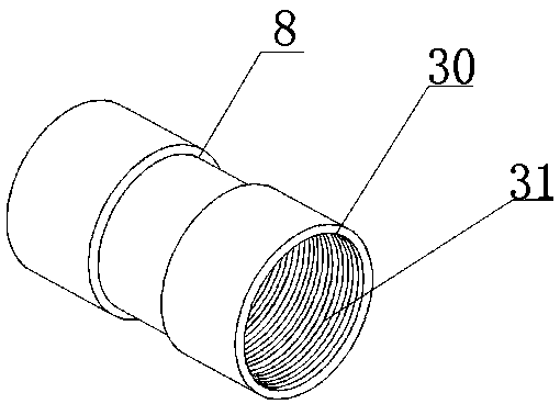
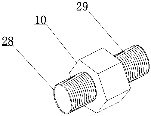
[0023] This RG rotary guide includes a rotary guide body, the rotary guide body includes a joint, a seal, a spring, a transposition mandrel 5, a splined piston 13 and a splined outer cylinder 12, and the joint includes an upper joint 1 and the lower joint 15, the seal includes a sealing outer cylinder 4, the spring includes an upper spring 11 and a lower spring 16, one end of the transposition mandrel 5 is fixedly connected to the upper joint 1, and the transposition mandrel 5 is connected to the upper A first O-ring 18 is connected between the joints 1, a double female joint 8 is connected to the other end of the transposition mandrel 5, and a third O-ring 18 is connected between the transposition mandrel 5 and the double female joint 8. O-ring 21, the lower mandrel 9 is connected to the right end of the double female joint 8, the fourth O-ring 22 is connected between the lower mandrel 9 and the double female joint 8, the right end of the lower mandrel 9 A pressure transmissi...

Embodiment 2

[0024] Embodiment 2: On the basis of Embodiment 1, the sealing outer cylinder 4 is a hollow cylindrical structure, and the inner upper spring 11 protects the lower mandrel 9 through the above structure.

Embodiment 3

[0025] Embodiment 3: On the basis of Embodiment 1, the number of anti-rotation pin 1 17 and anti-rotation pin 2 19 is 2, and the anti-rotation pin 1 17 is symmetrically distributed in the connection between the upper joint 1 and the uploading twist sleeve 2 The anti-rotation pins 2 19 are symmetrically distributed at the junction of the lower transmission twist sleeve 2 and the sealing outer cylinder 4, so as to ensure normal operation during use and effectively improve work efficiency.


PUM


Abstract

The invention provides an RG rotary guider and a using method thereof. The RG rotary guider comprises a rotary guider body, the rotary guider body comprises joints, a seal, springs, a transposition core shaft, a spline piston and a spline outer cylinder; the joints comprise the upper joint and the lower joint, the seal comprises a sealed outer cylinder, and the springs comprise the upper spring and the lower spring; one end of the transposition core shaft is fixedly connected with the upper joint, a first O-shaped ring is connected between the transposition core shaft and the upper joint, andthe other end of the transposition core shaft is connected with a double-nut joint; and a third O-shaped ring is connected between the transposition core shaft and the double-nut joint, the right endof the double-nut joint is connected with a lower core shaft, a fourth O-shaped ring is connected between the lower core shaft and the double-nut joint, the right end of the lower core shaft is connected with a pressure transmission nut, and the right end of the pressure transmission nut makes contact with the lower spring. The RG rotary guider is reasonable in design and suitable for popularization.

Description

technical field [0001] The invention relates to the field of rotary guide equipment, in particular to an RG rotary guide and a use method. Background technique [0002] Coiled tubing drilling operations are different from conventional drilling operations using drilling rigs and drill pipes. Because the coiled tubing body cannot rotate, it is necessary to turn the tool to adjust the tool orientation to ensure that the wellbore trajectory extends to the target area according to the design requirements. For example, the wellhead rotary guide proposed in Patent No. CN201020203336.5 prolongs the service time of the rubber core, but cannot make the rotary guide have a strong torque. When the downhole tool orientation needs to be reversed by coiled tubing sidetracking, the pipe string is pulled up to keep the drill bit away from the rock. Bit pressure reduced to zero. During circulation, the pressure drop of the motor can push the piston to rotate the pipe string. . The orienta...

Claims


Application Information

Patent Timeline
Patent Type & Authority Applications(China)
IPC IPC(8): E21B7/04
CPCE21B7/04E21B7/046
Inventor 孙虎白明伟曹欣陈家俊陈文博任斌张宁刚徐迎新杨红斌李绪宜谢涛席仲琛田军宁治军陈飞尹俊禄贾海平王科萌
Owner BC P INC CHINA NAT PETROLEUM CORP
Learn More