Constant-pressure type centrifugal pump

A centrifugal pump and formula calculation technology, which is applied in the field of constant pressure centrifugal pumps and fire pumps for high-rise buildings, can solve the problems of high failure rate, complicated control, and many equipments, and achieve head reduction, flow head curve flatness, expansion and high efficiency zone effect

Pending Publication Date: 2019-03-08
西安航天泵业有限公司
View PDF0 Cites 0 Cited by
  • Summary
  • Abstract
  • Description
  • Claims
  • Application Information

AI Technical Summary

Problems solved by technology

[0004] The purpose of the present invention is to solve the technical problems that the existing centrifugal pumps for fire protection are prone to overpressure, and the frequency conversion speed regulation water pump device uses many equipment, large investment, complicated control and high failure rate, and provides a constant pressure centrifugal pump. pumps for use as fire pumps

Method used


Image

  • Constant-pressure type centrifugal pump
  • Constant-pressure type centrifugal pump
  • Constant-pressure type centrifugal pump

Examples


Embodiment Construction

[0047] The present invention will be described in detail below in conjunction with the accompanying drawings and specific embodiments.

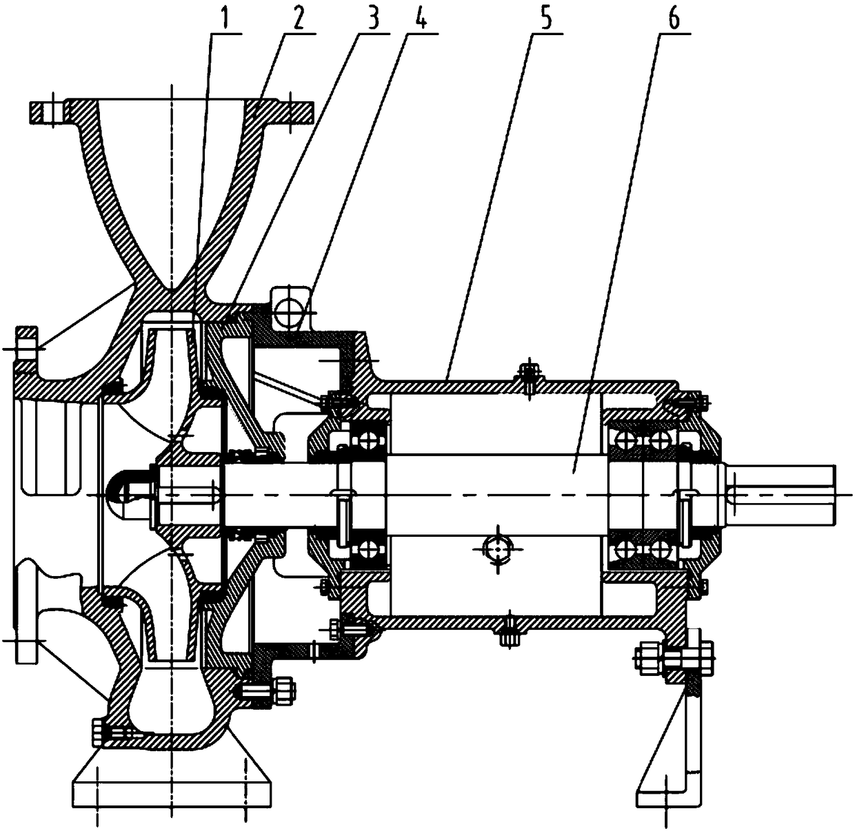
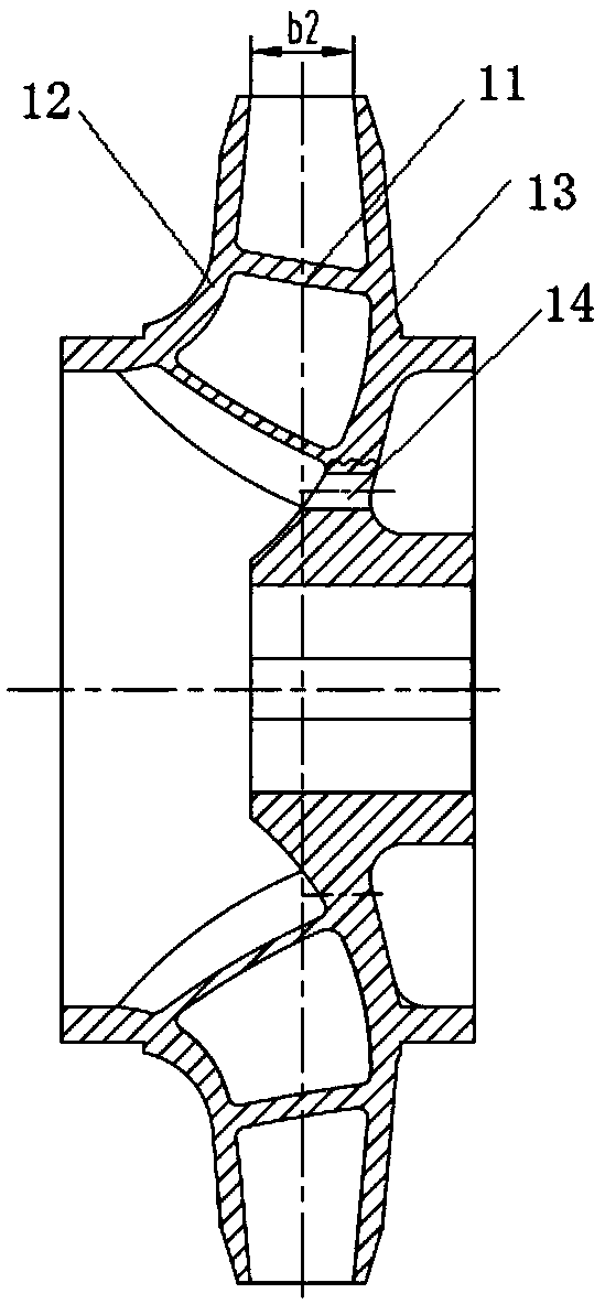
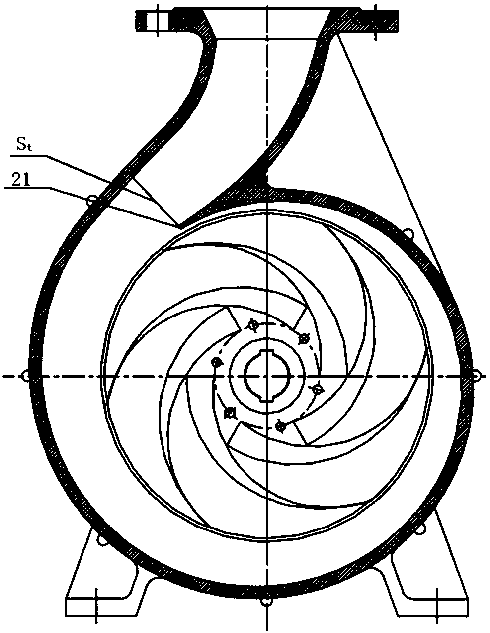
[0048] Such as figure 1 , figure 2 , image 3 , Figure 4 As shown, a constant pressure centrifugal pump of the present invention includes an impeller 1, a housing 2, a seal seat 3, a bracket 4, a bearing body part 5 and a main shaft 6; the impeller 1 is a centrifugal impeller, and the impeller in this embodiment The impeller 1 is a closed impeller, and the center of one side of the impeller 1 has an impeller axial water inlet coaxial with the impeller 1. The impeller 1 is installed on the main shaft 6 and is located in the casing 2. The impeller 1 and the drive shaft of the centrifugal pump Connected by a coupling; the shell 2 is a spiral shell structure, the spiral shell structure is composed of a spiral flow channel and a diffuser tube with a gradually increasing cross-sectional area, the impeller 1 is installed in the spiral flow chan...


PUM


Abstract

The invention relates to a high-rise building fire control pump, in particular to a constant-pressure type centrifugal pump, and aims at solving the technical problems that overpressure is likely to happen to an existing fire control centrifugal pump, but the amount of equipment used for a speed adjusting water pump device is large, the investment is large, control is complex, and the fault rate is high. The constant-pressure type centrifugal pump is provided and used as a fire control pump. The constant-pressure type centrifugal pump comprises an impeller, a shell and a main shaft, and the impeller is arranged on the main shaft and located in the shell. The outlet width of the impeller is about 1.05-1.15 times of the common centrifugal pump theoretical design width, the area of the fracture surfaces of a volute chamber is increased by 30% compared with the area according to the existing empirical formula design, and the throat area of the shell is 1.08-1.12 times of the throat area according to the existing empirical formula design. A flow lift curve of the constant-pressure type centrifugal pump is relatively flat, and the changing range of the lift between the zero flow and therated flow is smaller than 1.1 times of the rated lift.

Description

technical field [0001] The invention belongs to fire-fighting equipment, and relates to a fire-fighting pump for high-rise buildings, in particular to a constant-pressure centrifugal pump. Background technique [0002] At present, the fire-fighting system mostly uses centrifugal pumps or tangential pumps as fire-fighting pumps. The tangential pump has the problem of a hump in the flow-head curve, that is, one head corresponds to two flow points. When the pump is running, there will be a surge phenomenon of sometimes small flow and sometimes large flow. This is not allowed in fire pumps. , so it is not advisable to choose a tangential pump as a fire pump. [0003] The flow-head curve of traditional centrifugal pumps monotonously declines quickly, the head is higher at low flow rates, and the head drops faster at large flow rates, and the range of head changes is larger. When it is used as a fire pump, it is easy to appear in the fire protection system overpressure phenomeno...

Claims


Application Information

Patent Timeline
IPC IPC(8): F04D29/22F04D29/24F04D29/42
CPCF04D29/2216F04D29/242F04D29/426
Inventor 王凤梅朱保民张发杰杨沛蒋应喜冯思涛席悦张小龙杨晶盛涛卢登弟张振华王学青高榕泽田亚东
Owner 西安航天泵业有限公司
Why Eureka
Try Eureka