
Ore pulp sampling and iron grade signal collection device and method

A technology of signal acquisition and iron grade, applied in sampling devices, material magnetic variables, etc., can solve the problems of single sampling function and cumbersome process, and achieve the effect of avoiding measurement process, improving efficiency and easy operation.

Pending Publication Date: 2019-03-08
HARBIN UNIV OF SCI & TECH
View PDF0 Cites 0 Cited by
  • Summary
  • Abstract
  • Description
  • Claims
  • Application Information

AI Technical Summary

Problems solved by technology

[0003] The present invention solves the problem that the existing sampling device only has a single sampling function, and needs to be transferred to the laboratory to measure the iron grade of the ore pulp after sampling, resulting in cumbersome procedures.

Method used


Image

  • Ore pulp sampling and iron grade signal collection device and method
  • Ore pulp sampling and iron grade signal collection device and method
  • Ore pulp sampling and iron grade signal collection device and method

Examples


specific Embodiment approach 1

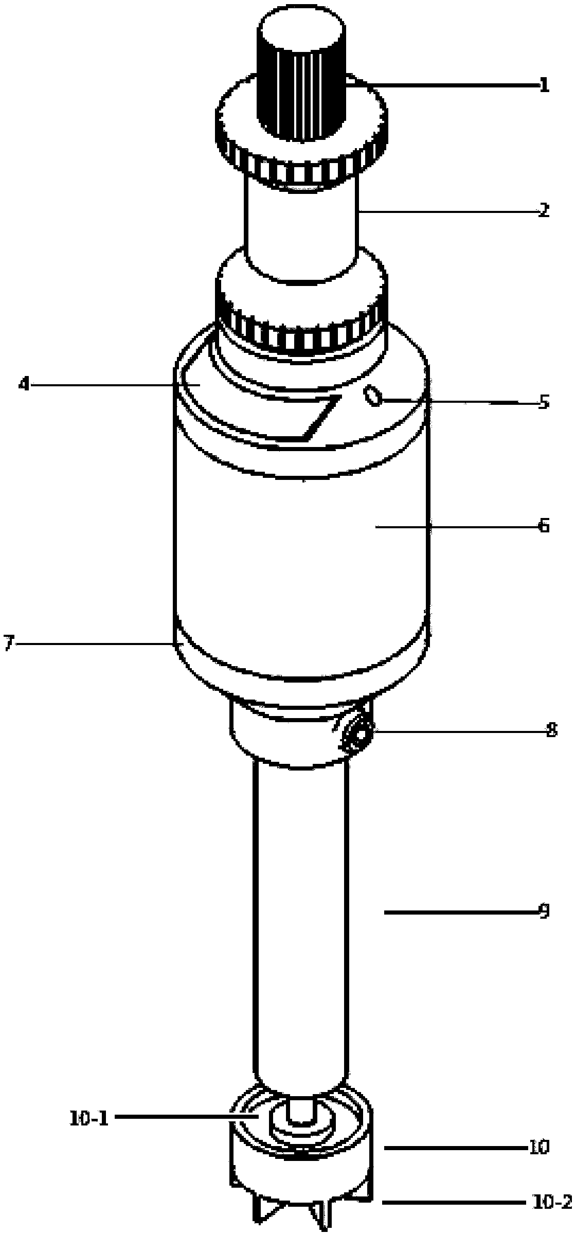
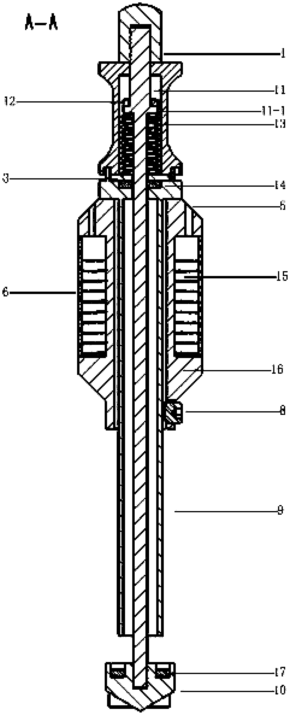
[0023] Specific implementation mode one: combine Figure 1 to Figure 3 Describe this embodiment, a kind of ore pulp sampling and iron grade signal acquisition device described in this embodiment includes dustproof cap 1, handle 2, sampling cylinder 9, measuring rod 11, compression spring 13 and sampling cylinder lower end cover 10, handle 2 The lower end of the measuring rod 11 is connected to the upper end of the sampling cylinder 9, the measuring rod 11 runs through the handle 2 and the sampling cylinder 9 from top to bottom, and the lower end of the measuring rod 11 is inserted into the upper surface of the lower end cover 10 of the sampling cylinder, and the dustproof cap 1 is set On the upper end of the measuring rod 11; said a kind of ore slurry sampling and iron grade signal acquisition device also includes a sensor measuring head 7 and a set screw 8, said sensor measuring head 7 is set on the outer side wall of the sampling cylinder 9 top, and the sensor measuring The ...

specific Embodiment approach 2

[0025] Specific implementation mode two: combination Figure 1 to Figure 3 Describe this embodiment, the sensor measuring head 7 described in this embodiment includes a keel 16, a glass observation window 4, a sensor coil 15, two lead holes 5 and a shielding outer layer 6, the outer wall of the keel 16 has an annular gap, and two lead wires The holes 5 are arranged symmetrically on the outer side wall of the upper end of the keel 16, the sensor coil 15 is wound in the annular gap of the keel 16, the two ends of the sensor coil 15 are respectively derived from the two lead holes 5, and the glass observation window 4 is arranged on two Between the lead holes 5 , the shielding outer layer 6 covers the annular gap of the keel 16 .

[0026] The keel 16 is made of non-metallic insulating material, and the enameled wire is wrapped around the annular gap of the keel 16 to form a sensor coil 15. The two ends of the sensor coil 15 are respectively derived from the two lead holes 5, whic...

specific Embodiment approach 3

[0028] Specific implementation mode three: combination Figure 1 to Figure 3 Describe this embodiment, the device described in this embodiment also includes a compression spring support plate 3 and a sealing washer 14, the compression spring support plate 3 and the sealing washer 14 are sequentially set on the measuring rod 11 from top to bottom, and the compression spring support plate 3 is located at the connection between the sampling cylinder 9 and the handle 2, and the sealing gasket 14 is located in the upper surface of the sampling cylinder 9.

[0029] It is set in this way to prevent the ore slurry from penetrating into the space where the compression spring 13 is located along the outer wall of the measuring rod 11 .

[0030] Other components and connections are the same as those in the first embodiment.


PUM


Abstract

The invention provides an ore pulp sampling and iron grade signal collection device and method, and relates to a sampling device and method. The device and the method aim at solving the problems thatthe existing sampling device only has a single sampling function; after sampling, the materials need to be transferred into a laboratory for measuring ore slurry iron grade, so that the work procedures are complicated. The device provided by the invention comprises a dustproof cap, a handle, a sampling tube, a measuring rod, a compression spring and a sampling tube lower end cover, wherein the lower end of the handle is connected with the upper end of the sampling tube; the measuring rod sequentially penetrates through the handle and the sampling tube from top to bottom; the lower end of the measuring rod is inserted into the upper surface of the lower end cover of the sampling tube; the dustproof cap sleeves the upper end of the measuring rod; the ore slurry sampling and iron grade signalcollection device further comprises a sensor measuring head and a fastening screw; the sensor measuring head sleeves the outer side wall of the upper part of the sampling tube; and the lower part ofthe sensor measuring head is fixedly connected with the sampling tube through the fastening screw. The device and the method provided by the invention are used in the technical field of industrial mineral separation.

Description

technical field [0001] The invention relates to a sampling device and method, in particular to an ore pulp sampling and iron grade signal acquisition device and method. Background technique [0002] In the process of industrial mineral processing, in order to determine the quality of iron ore pulp in different batches and processes, it is necessary to sample and analyze the pulp at different depths in the pulp tank in the mineral processing process. The results of the analysis and testing can provide data for optimizing the process flow and fine-tuning production equipment parameters For reference, the traditional slurry sampler only has a single sampling function, and after sampling, it needs to be transferred to the laboratory for measurement of the iron grade of the slurry. The laboratory chemical analysis method is accurate, but the process is cumbersome and the test cycle is long. Contents of the invention [0003] The present invention solves the problem that the exi...

Claims


Application Information

Patent Timeline
Patent Type & Authority Applications(China)
IPC IPC(8): G01N1/10G01N27/74
CPCG01N1/10G01N27/74
Inventor 王丽杰刘志强朱思露
Owner HARBIN UNIV OF SCI & TECH
Learn More