Battery core fixing structure for electric automobile and electric automobile

A technology for electric vehicles and fixed structures, applied to structural parts, electric power devices, circuits, etc., can solve problems such as weight increase, battery core heat dissipation and heat preservation maximization, electric vehicle fires, etc., to achieve maximum energy density and space utilization Maximize and enhance the effect of heat dissipation performance

Pending Publication Date: 2019-03-08
广州市垠瀚能源科技有限公司
View PDF12 Cites 2 Cited by
  • Summary
  • Abstract
  • Description
  • Claims
  • Application Information

AI Technical Summary

Problems solved by technology

[0004] Considering the integrity and consistency of the battery module and battery PACK, reinforcement ribs and structural beams need to be added to the chassis, resulting in batteries that cannot be completely covered on the entire chassis, resulting in a large amount of battery installation. A lot of space wasted and weight increased in the car, which limits the energy density of the battery, affects the battery life of electric vehicles, and greatly restricts the battery life of electric vehicles in the future.
In addition, the design of battery modules and battery packs needs to consider the heat dissipation problem to avoid thermal runaway. However, due to the constraints of the current battery design itself, it is impossible to maximize the heat dissipation and heat preservation of the battery cells, which is prone to heat loss due to heat dissipation. Accidents in which electric vehicles caught fire due to loss of control
In addition, due to the different models, sizes and appearance designs of electric vehicles at this stage, battery modules and battery packs need to be redesigned for different vehicles, resulting in a lot of repetitive work

Method used


Image

  • Battery core fixing structure for electric automobile and electric automobile
  • Battery core fixing structure for electric automobile and electric automobile
  • Battery core fixing structure for electric automobile and electric automobile

Examples


Embodiment Construction

[0024] The specific implementation manners of the present invention will be further described in detail below in conjunction with the accompanying drawings and embodiments. The following examples are used to illustrate the present invention, but are not intended to limit the scope of the present invention.

[0025] In the description of the present invention, it should be noted that the orientation or positional relationship indicated by the terms "upper", "bottom", "inner", "outer" etc. is based on the orientation or positional relationship shown in the drawings, and is only for It is convenient to describe the present invention and simplify the description, but does not indicate or imply that the device or element referred to must have a specific orientation, be constructed and operate in a specific orientation, and thus should not be construed as limiting the present invention.

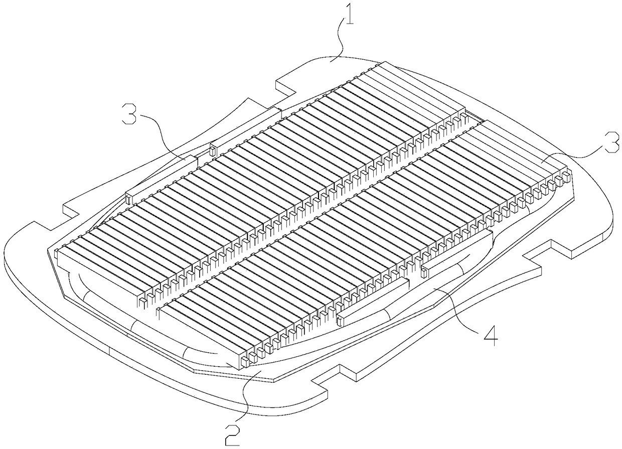
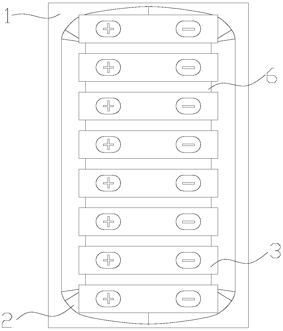
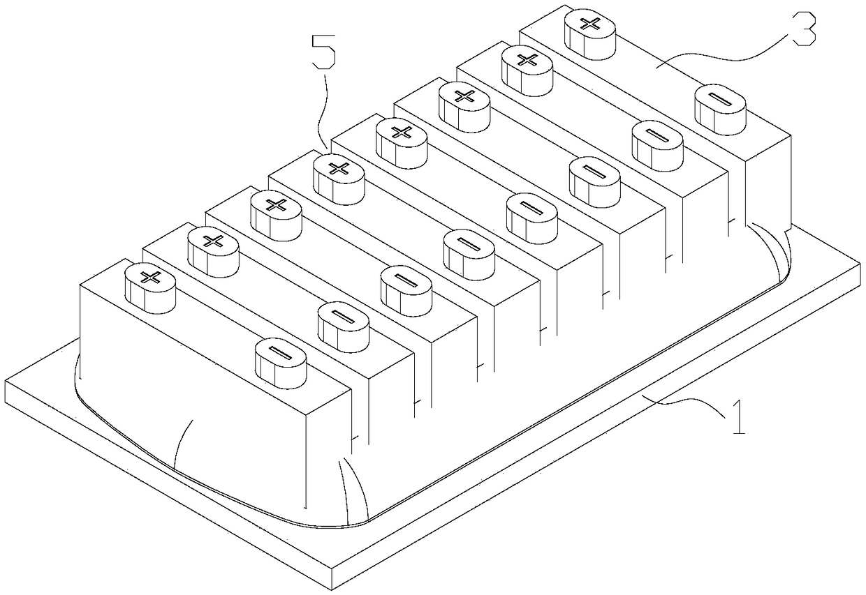
[0026] Such as Figure 1 to Figure 3 As shown, the present invention provides a battery cell f...


PUM


Abstract

The invention discloses a battery core fixing structure for an electric automobile. The fixing structure comprises an automobile chassis, a heat dissipation plate and a plurality of battery cores, wherein the heat dissipation plate is fixedly connected to the automobile chassis; the battery cores are arranged on the heat dissipation plate through a fixing material; each of the battery cores is a soft-packed battery core or a steel-shell battery core; and when each of the battery cores is the soft-packed battery core, a gap with 1-10 mm is reserved between the soft-packed battery cores. According to the battery core fixing structure for the electric automobile and the electric automobile provided by the invention, the heat dissipation efficiency is high; more battery cores can be arranged on the automobile chassis, and the energy density is high.

Description

technical field [0001] The invention relates to the technical field of batteries, in particular to a cell fixing structure of an electric vehicle and the electric vehicle. Background technique [0002] A cell refers to a single electrochemical cell containing positive and negative electrodes, including soft pack cells and steel shell cells. Battery PACK generally refers to a single battery component. For example, two batteries are connected in series to form a specific shape according to customer requirements. We call it battery PACK, which generally refers to a combined battery. A battery module is a multiple battery PACK composed of several to hundreds of battery cells connected in parallel and in series. In addition to the mechanical design part, a battery management system and a thermal management system can be added to form a relatively complete battery pack system. . [0003] With the gradual popularization of electric vehicles, people pay more and more attention to ...

Claims


Application Information

Patent Timeline
Patent Type & Authority Applications(China)
IPC IPC(8): H01M2/10H01M10/613H01M10/625H01M10/655H01M10/6554H01M10/6556H01M10/6568B60K1/04H01M50/249
CPCH01M10/613H01M10/625H01M10/655H01M10/6554H01M10/6556H01M10/6568B60K1/04H01M50/20Y02E60/10
Inventor 陈建浩谭德深张伟强
Owner 广州市垠瀚能源科技有限公司
Why Eureka
Try Eureka