Flexible guide drilling tool

A directional drilling, flexible technology, applied in the field of drilling, drilling, can solve the problems that cannot be achieved, drag the drill pressure, do not have the guiding function, etc., to achieve the effect of improving the passability, shortening the length and shortening the size

Inactive Publication Date: 2021-07-23
万晓跃
View PDF0 Cites 4 Cited by
  • Summary
  • Abstract
  • Description
  • Claims
  • Application Information

AI Technical Summary

Problems solved by technology

The maximum deflection rate that can be achieved by the above technologies is generally not more than 15° / 30 meters, and it is impossible to realize the controllable track short-radius directional drilling with a radius of curvature less than 60 meters
There are still many radial or short-radius drilling technologies that cannot effectively control the wellbore trajectory in the existing technology, and such technologies are not effective for the development and utilization of underground resources
However, for the field of extremely short-radius drilling with a turning radius of less than 10 meters, the existing radial drilling technology or short-radius drilling technology does not have the steering function and cannot realize the control of the wellbore trajectory
Because the currently used rotary steerable system is inherently unable to be bent, it is almost impossible to meet the actual needs of short-radius drilling, and it is impossible to achieve short-radius to extremely short-radius directional drilling under rotary drilling conditions
Other related products in the prior art also have the function of not being able to realize wellbore trajectory control under the condition of rotary drilling, resulting in a serious problem of dragging the bit pressure

Method used


Image

  • Flexible guide drilling tool
  • Flexible guide drilling tool
  • Flexible guide drilling tool

Examples


Embodiment Construction

[0067] In order to have a clearer understanding of the technical solutions, objectives and effects of the present invention, the specific implementation manners of the present invention will now be described with reference to the accompanying drawings. Among them, the use of adjective or adverbial modifiers "upper" and "lower", "inner" and "outer", "front" and "rear" is only for relative reference between groups of terms, and is not descriptive Any specific directional constraints on the modified term. "Front" and "rear" described herein refer to the front and rear along the drilling direction. In addition, the terms "first", "second" and so on are only used for descriptive purposes, and cannot be understood as indicating or implying relative importance or implicitly specifying the number of indicated technical features. Therefore, the definition of "first" , "second", etc. may expressly or implicitly include one or more of these features. In the description of the present i...


PUM


Abstract

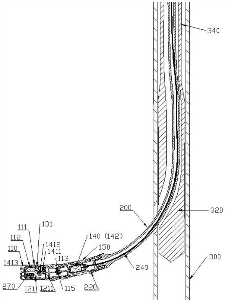
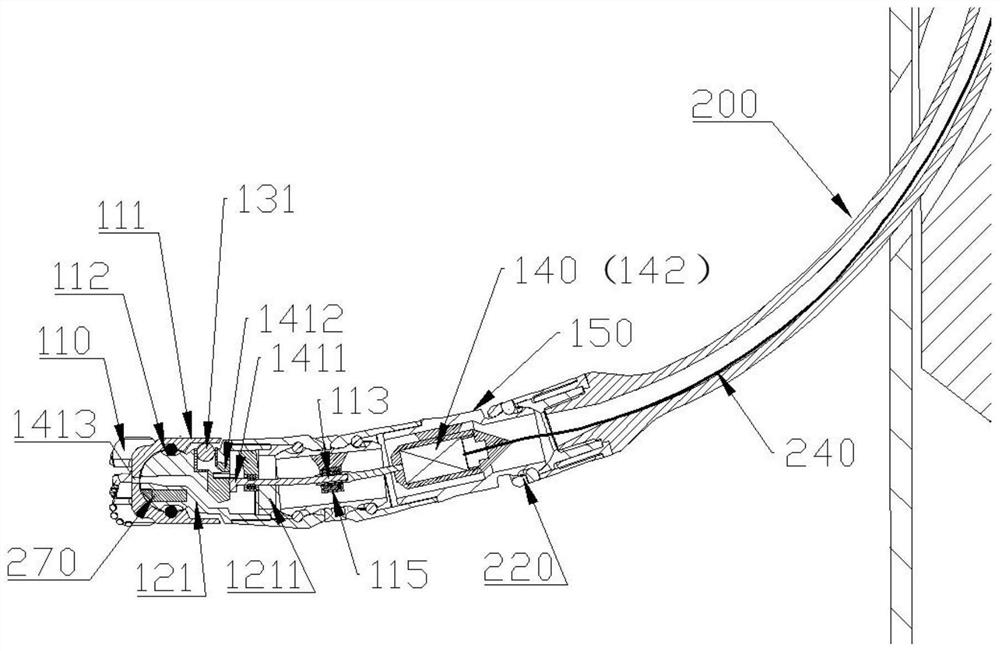
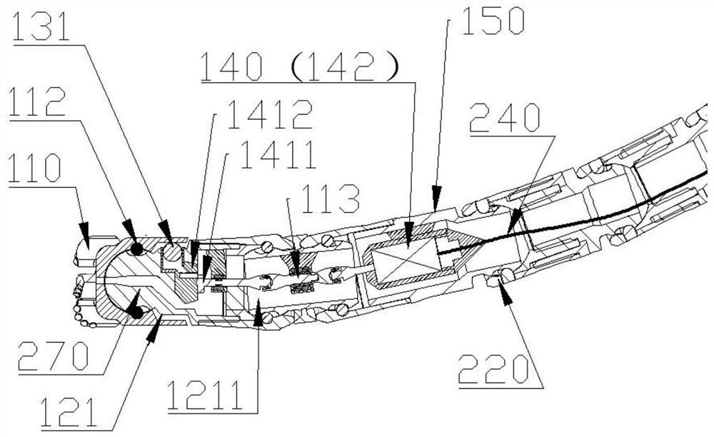
The invention discloses a flexible guide drilling tool, and relates to the technical field of well drilling and drilling. According to the flexible guide drilling tool, a flexible driving drilling column and a guide drilling short section are tripped in through a conveying pipe column, and the well track control problem in a small-hole and ultra-short-radius well is solved; by arranging a deflection guide mechanism, the flexible guide drilling tool can drive a drill bit to deflect in the preset direction under the rotary drilling condition; drilling power transmission is achieved through a plurality of bearing short sections connected through universal transmission mechanisms; the deflection guide mechanism and an electric drive actuator are arranged in the different functional short sections respectively, connection is achieved through a flexible bridging connecting rod, the length of the guide drilling section and the distance between all the universal transmission mechanisms are shortened to the maximum extent, and the control problem of the flexible guide drilling tool is solved. According to the flexible guide drilling tool, a short-radius-to-ultra-short-radius well hole can be drilled through a small hole, or guide drilling can be continuously carried out through the short-radius-to-ultra-short-radius well hole.

Description

technical field [0001] The invention relates to the technical field of drilling and drilling, in particular to a flexible guiding drilling tool. Background technique [0002] The invention relates to a drilling technology, which relates to the field of drilling and drilling technology. In particular, it is a device and method for realizing controllable track lateral drilling of small holes. In order to improve the injection or recovery effect of the permeable formation, improve the controllability of the fracturing fracture shape, and finally achieve the effect of cost reduction and efficiency increase. The existing steering drilling technologies mainly include downhole motor steering drilling technology and rotary steering drilling technology. The maximum build-up rate that can be achieved by the above-mentioned technologies is generally not more than 15° / 30 meters, and it is impossible to realize short-radius steerable drilling with a controllable trajectory and a radius...

Claims


Application Information

Patent Timeline
Patent Type & Authority Applications(China)
IPC IPC(8): E21B7/04E21B17/20E21B17/05E21B10/42E21B10/60
CPCE21B7/04E21B10/42E21B10/602E21B17/05E21B17/20E21B17/206
Inventor 徐梓辰万晓跃
Owner 万晓跃
Why Eureka
Try Eureka