Check patentability & draft patents in minutes with Patsnap Eureka AI!

A control method for intermittent mode of two-stage converter

A control method and technology of cascading converters, which are applied in control/regulation systems, conversion of DC power input to DC power output, instruments, etc., can solve problems such as damage to light-load efficiency, and the realization of zero-voltage turn-on cannot be guaranteed. The effect of improving efficiency

Active Publication Date: 2020-02-21
SOUTHEAST UNIV +1
View PDF5 Cites 0 Cited by
  • Summary
  • Abstract
  • Description
  • Claims
  • Application Information

AI Technical Summary

Problems solved by technology

[0004] However, the above-mentioned intermittent working mode still has some deficiencies
For example, when the ON signal is generated, the current of the front-stage inductor is zero, and the waveform of the front-stage inductor current needs multiple cycles to reach a steady state. That is to say, in these cycles, the upper and lower tubes of the front bridge arm cannot guarantee Implementation of zero-voltage turn-on, which compromises efficiency at light loads

Method used


Image

  • A control method for intermittent mode of two-stage converter
  • A control method for intermittent mode of two-stage converter
  • A control method for intermittent mode of two-stage converter

Examples


Embodiment Construction

[0023] The present invention will be further described below in conjunction with the accompanying drawings and embodiments.

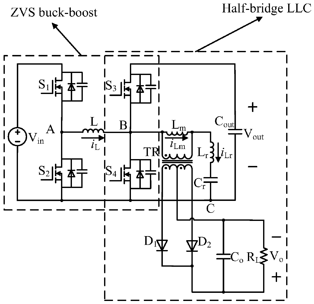
[0024] figure 1 It is the schematic diagram of the two-stage Buck-Boost LLC converter, in which S1-S4 are the MOS tubes on the primary side, the inductance L is the Buck-Boost inductance of the front stage, Lm is the excitation inductance, Lr and Cr are the resonant inductance and the resonance capacitance. D1 and D2 are rectifier tubes on the secondary side, Vin is the input voltage, Vout is the output voltage of the previous Buck-Boost stage, and Vo is the output voltage.

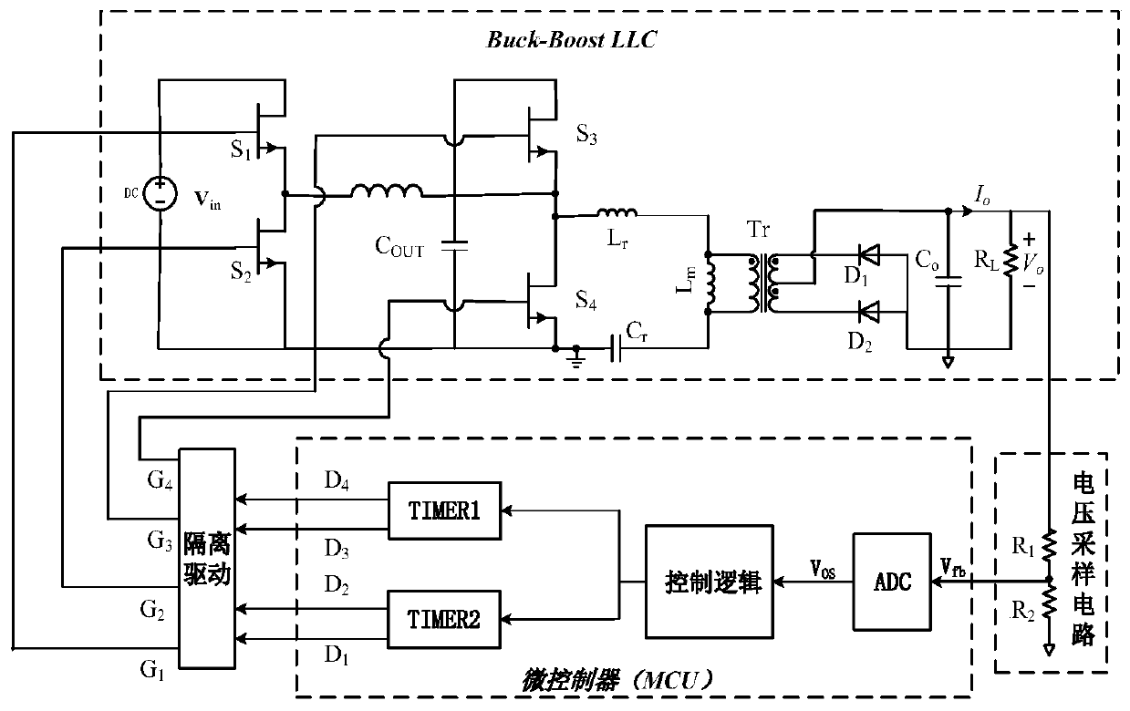
[0025] figure 2 It is the control block diagram of the two-stage Buck-Boost LLC converter, which is composed of two-stage converter circuit, output voltage sampling circuit and microcontroller (MCU). The voltage sampling circuit samples the output voltage V o Get the divided voltage feedback signal V fb and input it to the microcontroller’s built-in analog-to-digital converter...


PUM


Abstract

The invention discloses a control method for an intermittent mode of a two-stage converter. When the Buck-Boost LLC two-stage converter works in the intermittent mode, at the beginning of each intermittent mode period, a microcontroller configures a timer to trigger a one-shoe mode once and controls the timer to generate a set of four-pre-regulated pulse width signals; four switch tubes S1-S4 of the converter are controlled after isolation drive, thereby enabling the S1 driving signal to be "low", the S2 driving signal to be "high", the S3 driving signal to be "high", and the S4 driving signalto be "low"; and therefore, a front-stage inductance current is pre-regulated to a preset negative value from zero. After four pre-regulated pulse widths, the microcontroller configures the timer towork in a multi-periodic mode. Through the added four pre-regulated pulse widths, the front-stage inductance current rapidly enters a stable state, and the zero voltage switch-on of the front-stage switch tube is guaranteed, so that the efficiency of the converter in the intermittent mode is improved.

Description

technical field [0001] The invention relates to a Buck-Boost LLC converter, in particular to a control method for an intermittent mode of a Buck-Boost LLC two-stage converter. Background technique [0002] The LLC resonant converter can realize zero-voltage turn-on of the switch tube and zero-current turn-off of the synchronous rectifier tube in the full load range, thereby reducing switching loss and improving efficiency. However, the LLC resonant converter adopts frequency conversion control. When the gain range is wide, the switching frequency range is also wide, which is not conducive to the design of magnetic components and electromagnetic interference. However, the Buck-Boost LLC two-stage converter adopts cascaded Buck-Boost and LLC of the same level. The latter stage LLC works at the resonant frequency point, and the gain is adjusted by adjusting the front stage Buck-Boost, which can ensure the In the case that the tube realizes zero voltage turn-on, it still has a ...

Claims


Application Information

Patent Timeline
Patent Type & Authority Patents(China)
IPC IPC(8): H02M3/335H02M3/158
CPCH02M3/1582H02M3/33569Y02B70/10
Inventor 孙伟锋詹成旺钱钦松王廷营廖良闯唐海瑞时龙兴
Owner SOUTHEAST UNIV
Features
  • R&D
  • Intellectual Property
  • Life Sciences
  • Materials
  • Tech Scout
  • Unparalleled Data Quality
  • Higher Quality Content
  • 60% Fewer Hallucinations
Learn More