Camera module and terminal

A camera module and terminal technology, applied in image communication, TV, color TV, etc., can solve the problem of large head size of the lens module, and achieve the effect of compact structure, convenient assembly, and reduced components

Pending Publication Date: 2019-03-08
KUNSHAN Q TECH CO LTD
View PDF7 Cites 6 Cited by
  • Summary
  • Abstract
  • Description
  • Claims
  • Application Information

AI Technical Summary

Problems solved by technology

Therefore, the head size of the lens module with this structure is relatively large

Method used


Image

  • Camera module and terminal
  • Camera module and terminal
  • Camera module and terminal

Examples


Embodiment Construction

[0023] The specific implementation manners of the present invention will be further described in detail below in conjunction with the accompanying drawings and embodiments. The following examples are used to illustrate the present invention, but are not intended to limit the scope of the present invention.

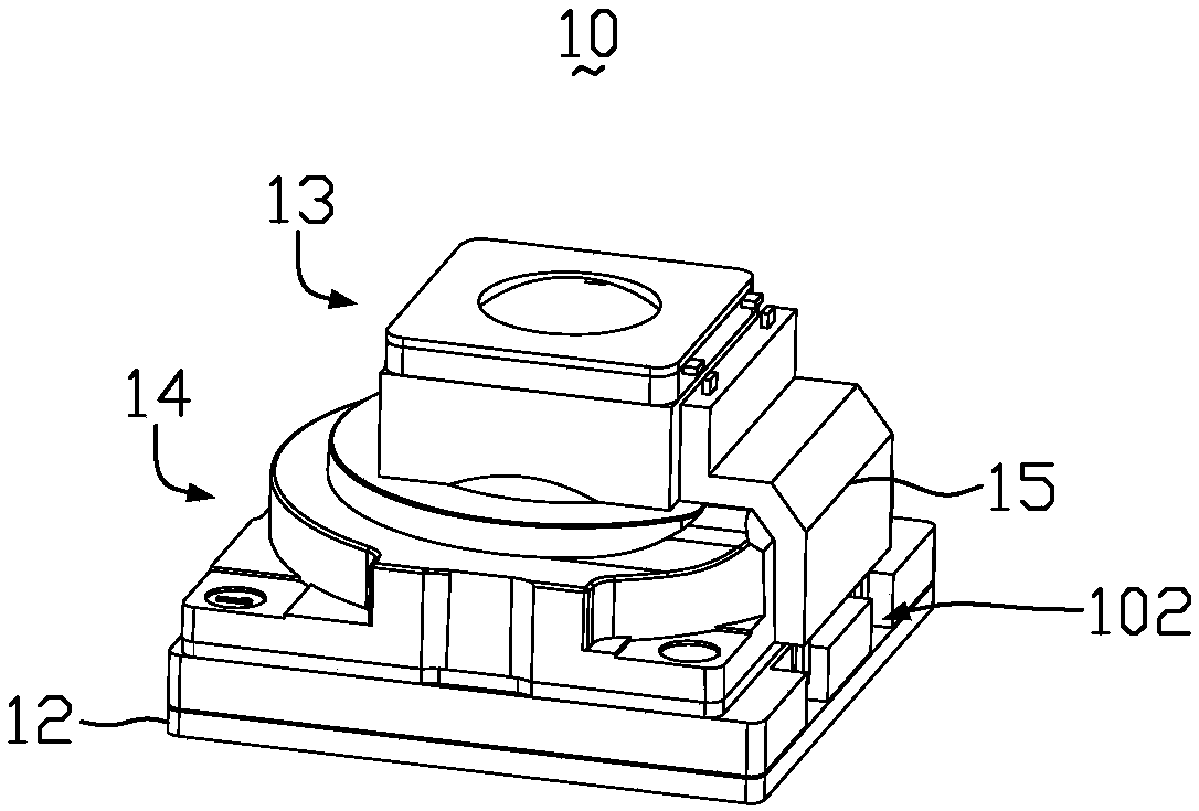
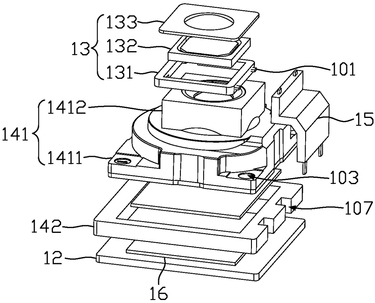
[0024] figure 1 It is a schematic structural diagram of the camera module according to the first embodiment of the present invention. figure 2 for figure 1 An exploded view of the camera module in the middle. Such as figure 1 and figure 2 As shown, the camera module 10 includes a circuit substrate 12 , an adjustable lens module 13 , a lens 14 , an auxiliary block 15 and a sensor 16 . The lens 14 is arranged on the circuit substrate 12, the auxiliary block 15 includes a body 151 and a conductor 152 wrapped in the body 151, the conductor 152 is electrically connected between the adjustable lens module 13 and the circuit substrate 12, and the auxiliary block 15 Locate...


PUM


Abstract

The invention relates to a camera module, which comprises a circuit board. The camera module also comprises an adjustable lens module, a lens and an auxiliary block. The lens is arranged on the circuit board; the adjustable lens module comprises a lens outer frame and a lens body; the lens outer frame is fixed to the lens; the lens body is arranged in the lens outer frame; one side of the lens outer frame is provided with a first conductive position; one side of the circuit board is provided with a second conductive position; the auxiliary block comprises a conductive body; one end of the conductive body is electrically connected with the first conductive position and the other end is electrically connected with the second conductive position so as to connect the lens outer frame and the circuit board electrically. The lens outer frame of the camera module in the invention is fixed on the lens; the lens body is electrically connected with the circuit board through the auxiliary block;the lens is arranged on the circuit board, thereby reducing elements of the camera module and further reducing the size of the head of the camera module; the structure is simpler; and the reliabilityis improved. The camera module in the invention relates to a terminal as well.

Description

technical field [0001] The invention relates to the technical field of imaging equipment, in particular to a camera module and a terminal. Background technique [0002] At present, most camera modules in mobile phones use voice coil motors to achieve focusing. The components of conventional voice coil motors are carriers, upper and lower springs, magnets, coils, bases and casings. The magnet itself will generate a magnetic field, and the coil will generate a current when it is energized. The magnetic field and the current will generate an ampere force to realize the up and down movement of the carrier, and drive the up and down stroke of the carrier by changing the magnitude of the current. The movement of the lens driven by the carrier realizes the autofocus function. The disadvantage is that due to the large size of the inherent devices such as the coil and the magnet, the structure is complex, and the processing technology is complicated. When multiple motors exist at the...

Claims


Application Information

Patent Timeline
Patent Type & Authority Applications(China)
IPC IPC(8): H04N5/225H04M1/02
CPCH04M1/0264H04N23/50H04N23/54H04N23/57H04N23/55G02B5/22G02B26/0825
Inventor 徐爱新黄捷徐炼孟伟黄庆跃
Owner KUNSHAN Q TECH CO LTD
Why Eureka
Try Eureka