
5-shaft linkage calibrating method of laser drilling machine

A technology of laser drilling machine and calibration method, applied in laser welding equipment, welding equipment, metal processing equipment, etc., can solve problems such as deformation, corrosion, lack of 5-axis linkage calibration method, etc.

Active Publication Date: 2019-03-12
AECC AVIATION POWER CO LTD
View PDF7 Cites 10 Cited by
  • Summary
  • Abstract
  • Description
  • Claims
  • Application Information

AI Technical Summary

Problems solved by technology

[0002] Laser drilling equipment must perform 5-axis linkage calibration after the replacement of head parts, optical devices or head collision, otherwise it will lead to quality problems of laser drilling and laser slit position offset
[0003] For old equipment, the original equipment used for laser beam 5-axis calibration is not used for a long time, rusted and deformed, and cannot truly reflect the real error situation. At the same time, due to the replacement of equipment, the spare parts of the original calibration equipment can no longer be purchased, so laser drilling In the process of using the equipment, it needs to rely on experienced operators to complete repeated tests. There is a lack of a simple and effective 5-axis linkage calibration method to verify the calibration results. There are hidden dangers in the quality of laser drilling and cutting workpieces.

Method used


Image

  • 5-shaft linkage calibrating method of laser drilling machine
  • 5-shaft linkage calibrating method of laser drilling machine
  • 5-shaft linkage calibrating method of laser drilling machine

Examples


Embodiment Construction

[0049] The present invention will be further described in detail below in conjunction with the accompanying drawings, which are explanations rather than limitations of the present invention.

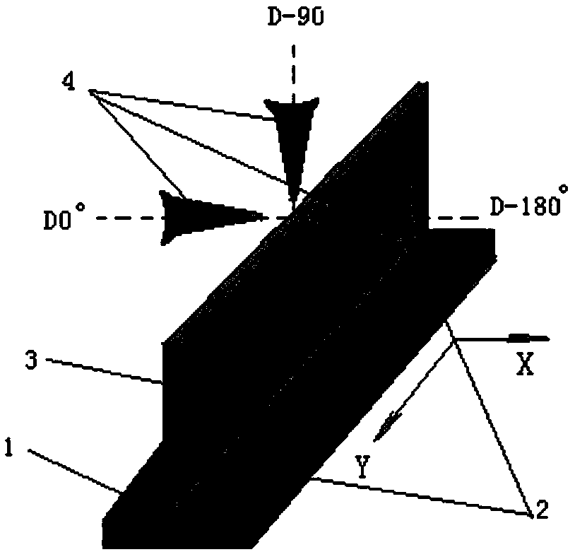
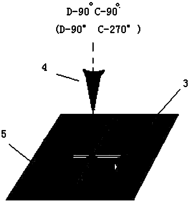
[0050] A 5-axis linkage calibration method for a laser drilling machine. It should be noted that in the calibration process, the D-axis needs to be calibrated first, and then the C-axis needs to be calibrated, so that the compensation value can take effect. Secondly, during the calibration process of the laser drilling machine, the spatial coordinates of the 5-axis linkage change greatly, so it is necessary to clean up the surroundings of the workbench in advance to avoid interference or collision.

[0051] Definition: the D axis is the rotation axis that rotates around any axis in the XY plane,

[0052] D-axis rotation The laser beam is irradiated vertically downward, the D-axis is -90°, the D-axis rotates counterclockwise to the horizontal state is 0°, and the D-axis rotates clockwise ...


PUM

PropertyMeasurementUnit
Thicknessaaaaaaaaaa

Abstract

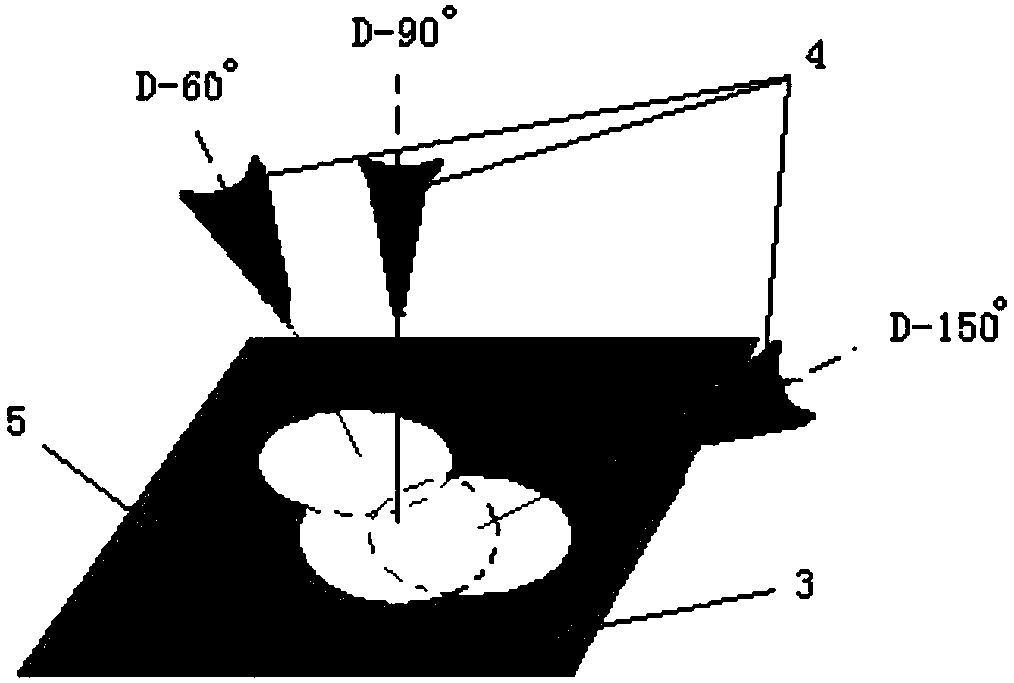
The invention discloses a 5-shaft linkage calibrating method of a laser drilling machine. A base is fixed on a worktable surface of a machine tool; in a 5-shaft linkage function state, a system controls a laser nozzle to drill a special stainless steel sample plate by different angles to realize the offset compensation of the radius of a D shaft and the zero point. Then, a magnet is adopted to firmly and horizontally absorb the special stainless steel sample plate on the worktable surface; according to the calibrating flow of a C shaft, the system controls the laser nozzle to drill a plane ofthe special stainless steel sample plate by different angles; and the hole deviation of holes is measured to realize the offset compensation of the radius of the C shaft and the zero point. The calibrating method adopts simple laser drilling tests, and can observes approaching or overlapping of the circle point centers of round small holes machined by different angles to conveniently detect the 5-shaft calibrating effect, so that the 5-shaft linkage deviation problem can be timely discovered and rectified, hidden troubles are removed in a bud state, and the laser drilling and cutting quality is effectively guaranteed.

Description

technical field [0001] The invention belongs to the field of industrial laser processing machine tools, and relates to the calibration of 5-axis linkage functions of laser processing equipment to improve the accuracy of laser drilling. Background technique [0002] Laser drilling equipment must perform 5-axis linkage calibration after replacing head parts, optical devices or head collision, otherwise it will lead to quality problems of laser drilling and laser slit position offset. [0003] For old equipment, the original equipment used for laser beam 5-axis calibration is not used for a long time, rusted and deformed, and cannot truly reflect the real error situation. At the same time, due to the replacement of equipment, the spare parts of the original calibration equipment can no longer be purchased, so laser drilling During the use of the equipment, it needs to rely on experienced operators to complete repeated tests. There is a lack of a simple and effective 5-axis link...

Claims


Application Information

Patent Timeline
IPC IPC(8): B23K26/382B23K26/70
CPCB23K26/382B23K26/702
Inventor 张维权罗斌刘佳张玮崔宗凯王斌郑榜伟田雅旭
Owner AECC AVIATION POWER CO LTD
Learn More