Core rod structure for floating supporting of metal hollow body

A floating support and hollow body technology, applied in printing, rotary printing machines, printing machines, etc., can solve the problems of increased difficulty in adjustment, increased heating and wear of support bearings, and difficulty in realization, saving time and simplifying type change operations , cost reduction effect

Pending Publication Date: 2019-03-12
SUZHOU SLAC PRECISION EQUIP CO LTD +1
View PDF7 Cites 0 Cited by
  • Summary
  • Abstract
  • Description
  • Claims
  • Application Information

AI Technical Summary

Problems solved by technology

[0007] However, in the scheme two of the above-mentioned prior art, there is no detailed requirement on the position of the bearing support. Therefore, when the scheme two is implemented, the printing pressure will be uneven during the printing process, that is, the automatic alignment cannot be effectively realized. allow
At this time, the original intention of the scheme design will not be achieved. At the same time, due to the bearing support bearing the bending moment, the uneven force will aggravate the heating and wear of the bearing unit in the above bearing assembly, and seriously reduce its service life.
[0008] On the other hand, the scheme two of the above-mentioned prior art can only be realized in the following three ways when producing tank types with different tank heights:
[0009] 1. Replace the mandrel shaft, and at the same time ensure that the relative axial position of the front end of the mandrel in the equipment remains unchanged, only change the length of the outer cylindrical surface of the mandrel in contact with the metal tank, and at the same time make the printing pressure center in the printing process On the support point of the mandrel shaft to the mandrel; since the mandrel shaft needs to be replaced, it will greatly increase the cost of parts, labor costs and time costs;
[0010] 2. Do not replace the mandrel shaft, only change the axial position of the front end of the mandrel in the equipment and the length of the contact between the outer cylindrical surface of the mandrel and the metal tank, and at the same time make the printing pressure center during the printing process lie between the mandrel shaft and the core The support point of the rod; this method changes the axial position of the front end of the mandrel, which is equivalent to changing the axial position of the tank mouth when the equipment enters the tank. The conveying line is adapted to the change of the position of the tank mouth, so the adjustment is more difficult, even difficult to realize, and the time and labor costs are greatly increased;
[0011] 3. Without replacing the mandrel shaft, the axial position of the front end of the mandrel remains unchanged, only the length of the contact between the outer cylindrical surface of the mandrel and the metal can is changed; but at this time, it is difficult to ensure that the printing pressure center is still located at the support center when the metal can is printed Within the range, it is impossible to guarantee the uniform distribution of printing pressure along the axial direction of the metal tank, and it will also greatly increase the heat and wear of the support bearing, reducing the service life of the parts
[0012] It can be seen that the above three tank height change methods all have relatively large defects, and it is basically difficult to implement them reliably in actual production.

Method used


Image

  • Core rod structure for floating supporting of metal hollow body
  • Core rod structure for floating supporting of metal hollow body
  • Core rod structure for floating supporting of metal hollow body

Examples


Embodiment

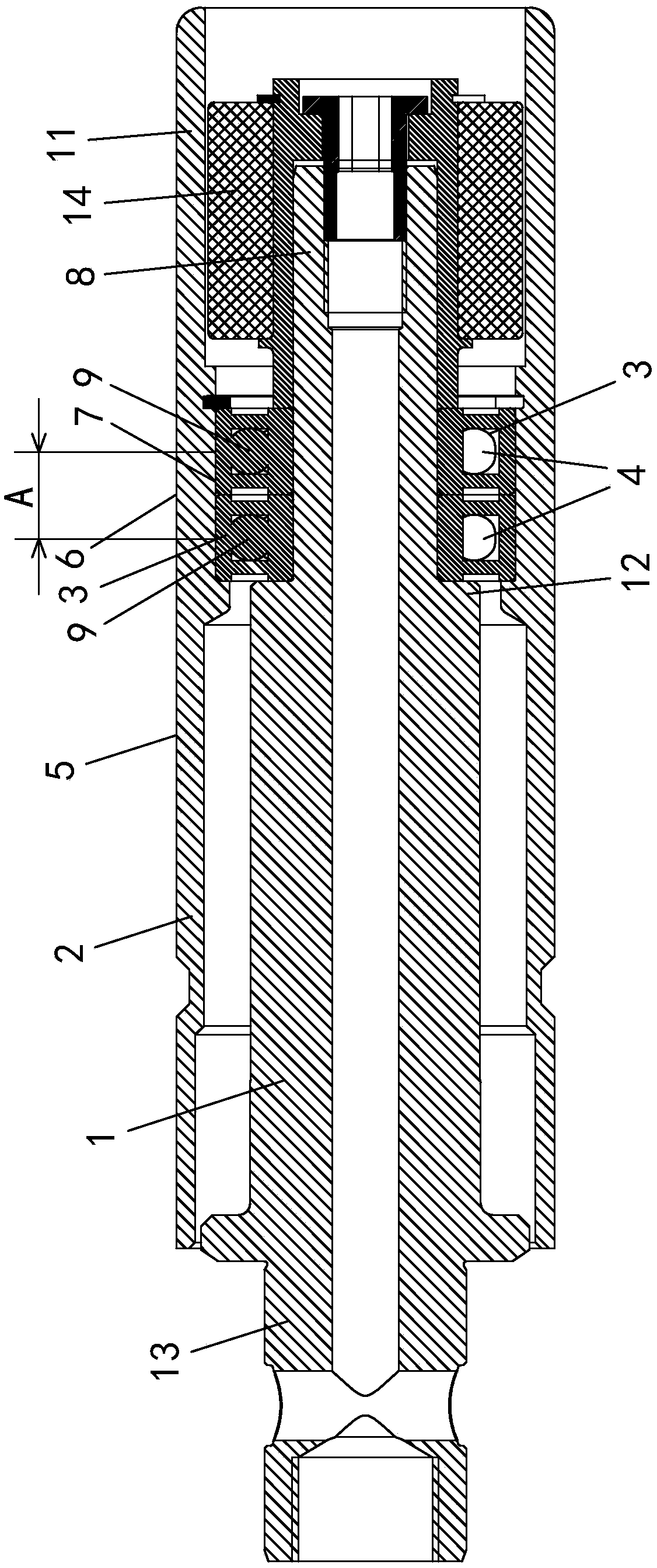
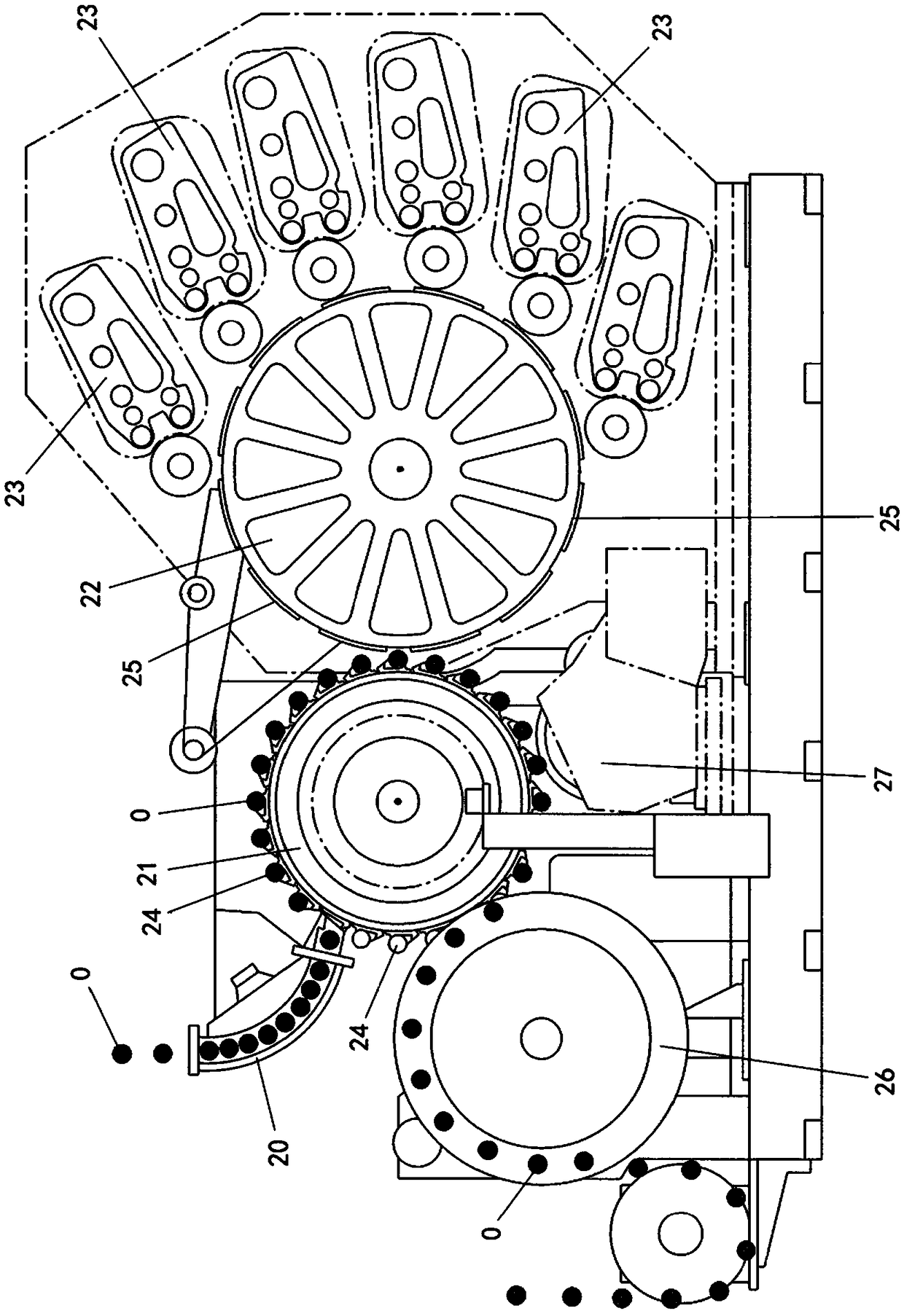
[0064] Example: see attached figure 1 And attached Figure 3~6 As shown, it is a core rod structure for floating supporting metal hollow body, which is used as figure 2 In the printing device shown, the structure of the printing device is not directly related to the present invention, and is only used as an example for the implementation of the present invention, so the protection scope of the present invention cannot be limited by this. In addition to printing equipment, the present invention can also be applied to other can forming processes (such as can body roll pattern forming, etc.), and the specific equipment is not illustrated with the drawings.

[0065] In this embodiment, the metal hollow body may specifically be a metal can 0.

[0066] Such as figure 2 As shown, the printing equipment is used for surface printing of a metal can 0, and the equipment mainly includes a can feeding mechanism 20, a mandrel turntable 21, a printing and bonding wheel 22, and a plurality of ink...


PUM


Abstract

The invention provides a core rod structure for floating supporting of a metal hollow body. The core rod structure comprises a core rod shaft, a core rod and a bearing assembly, wherein the core rod shaft is of a long and thin rotary body structure; the core rod is of a hollow cylinder structure, is coaxially mounted on the core rod shaft in a sleeving mode and rotates around the longitudinal axisof the core rod shaft; the bearing assembly is connected between the core rod and the core rod shaft; the periphery of the core rod is provided with a pressure bearing surface used for bearing printing pressure generated in the printing process; the pressure bearing center of the pressure bearing surface is located on a supporting part of the bearing assembly on the core rod. According to the core rod structure, the support part of the bearing assembly is aligned with the bearing center of the pressure bearing surface of the core rod; through the specific supporting arrangement, it can be ensured that the printing pressure of the core rod is uniformly distributed along the longitudinal axis; according to the design, the position of the bearing assembly is adjustable along the longitudinalaxis of the core rod shaft so that the position of the supporting part of the bearing assembly can be adjusted to enable the supporting part of the bearing assembly to be capable of being aligned with core rods with different pressure bearing centers; moreover, there is no need to adjust the axial position of the front end of the core rod, type changing operation is simplified, the time is saved,and the cost is reduced.

Description

Technical field [0001] The invention relates to the technical field of processing of metal hollow bodies, in particular to a core rod structure for floating support during the surface printing process of the metal hollow body or other can forming processes (such as can body knurling forming, etc.). Background technique [0002] The metal hollow body is a metal cylindrical body with an open end, such as metal cans and power battery shells. Take metal cans (two-piece cans made of iron, aluminum, etc.) as an example. When printing metal cans on the surface, the metal cans need to be sleeved on a core rod structure, and the metal cans are printed through the core rod structure. The supporting role. In the printing process, the outer surface of the interacting mandrel and the outer surface of the printing wheel of the printing press are required to be parallel to each other and adhere to each other so as to achieve uniform printing pressure at the can body along its longitudinal axis...

Claims


Application Information

Patent Timeline
Patent Type & Authority Applications(China)
IPC IPC(8): B41F17/22
CPCB41F17/22
Inventor 安旭刘丙新宋华王引
Owner SUZHOU SLAC PRECISION EQUIP CO LTD
Why Eureka
Try Eureka