Back-up image system with camera adjustable in angle

A reversing image and camera technology, which is applied to vehicle components, optical observation devices, transportation and packaging, etc., can solve the problems of narrowing viewing range, unadjustable angle, and single function, so as to reduce visual blind spots and improve reversing safety , the effect of expanding the viewfinder range

Pending Publication Date: 2019-03-12
CHANGCHUN UNIV OF TECH
View PDF6 Cites 12 Cited by
  • Summary
  • Abstract
  • Description
  • Claims
  • Application Information

AI Technical Summary

Problems solved by technology

As an important part of the reversing imaging system, the camera is usually fixedly installed in the center of the rear of the vehicle, facing the rear of the vehicle, and its angle cannot be adjusted; when the vehicle is reversing to the rear, the viewing range of the camera can meet the requirements. When turning, the driver often pays more attention to the scene behind the vehicle, which will create a blind spot on the inside of the curve; at the same time, when the vehicle reverses uphill, the camera’s viewing range will be reduced due to the slope, so there will be a big problem. security risks
[0003] In the existing patent application number 201220366172.7, an angle-adjustable reversing camera device is disclosed, which can judge the turning direction of the car when reversing according to the output signal of the steering wheel angle sensor, and automatically adjust the direction of the reversing camera through the horizontal adjustment motor. The heading angle (the angle between the projection of the optical axis of the reversing camera on the horizontal plane and the longitudinal axis of the car), but the automatic adjustment of the pitch angle of the reversing camera (the angle between the optical axis of the reversing camera and the horizontal plane) cannot be realized
In addition, the existing reversing camera system is only used when reversing, and has a single function, which needs to be further developed

Method used


Image

  • Back-up image system with camera adjustable in angle
  • Back-up image system with camera adjustable in angle
  • Back-up image system with camera adjustable in angle

Examples


Embodiment Construction

[0013] In order to deepen the understanding of the present invention, the present invention will be further described below in conjunction with the accompanying drawings.

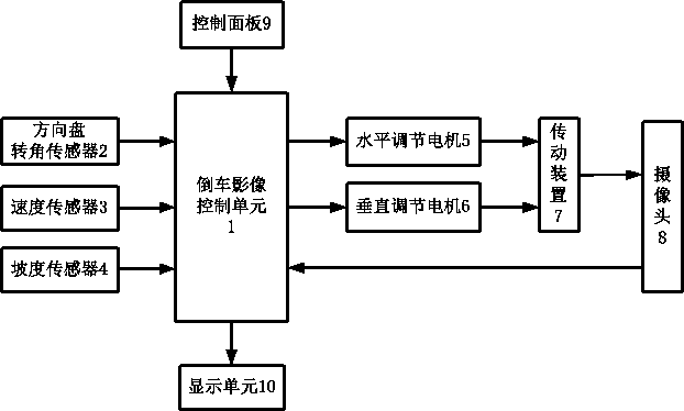
[0014] Such as figure 1 As shown, a reversing image system with an adjustable camera angle mainly includes a reversing image control unit 1, a steering wheel angle sensor 2, a speed sensor 3, a slope sensor 4, a horizontal adjustment motor 5, a vertical adjustment motor 6, a transmission device 7, and a camera 8. The control panel 9, the display unit 10, and the input terminals of the reversing image control unit 1 are respectively connected with the steering wheel angle sensor 2 installed on the steering column to detect the steering wheel's rotation direction, rotation angle and speed, and communicate with the steering wheel installed on the transmission. The speed sensor 3 is connected to detect the driving speed of the vehicle, and is connected to the slope sensor 4 installed near the center of mass of ...


PUM


Abstract

The invention relates to the technical field of automobile electronics and provides a back-up image system with a camera adjustable in angle. The back-up image system mainly comprises a back-up imagecontrol unit, a steering wheel rotating angle sensor, a speed sensor, a gradient sensor, a horizontal adjusting motor, a vertical adjusting motor, a transmission device, the camera, a control panel and a display unit. The back-up image control unit can automatically adjust the heading angle and pitch angle of the camera according to signals detected by the steering wheel rotating angle sensor, thespeed sensor and the gradient sensor, and the heading angle and the pitch angle can also be adjusted manually through the control panel. According to the system, the angle of the camera can be adjusted automatically or manually, a visual blind area of the inner side of a curve during back-up and steering can be reduced, the viewing range of the camera when a car backs up to climb a slope can be enlarged, and the back-up safety is improved. Meanwhile, under a special condition, the system can also be used for observing the scene behind the car and is convenient and practical.

Description

technical field [0001] The invention relates to the technical field of automotive electronics, in particular to a reversing image system with an adjustable camera angle. Background technique [0002] Reversing image is a common reversing assistance system. When the vehicle is in reverse gear, the reversing image system will automatically connect to the camera and display the rear image information collected by the camera on the display screen, which is convenient for the driver to observe and grasp. Rear traffic. As an important part of the reversing imaging system, the camera is usually fixedly installed in the center of the rear of the vehicle, facing the rear of the vehicle, and its angle cannot be adjusted; when the vehicle is reversing to the rear, the viewing range of the camera can meet the requirements. When turning, the driver often pays more attention to the scene behind the vehicle, which will create a blind spot on the inside of the curve; at the same time, when...

Claims


Application Information

Patent Timeline
Patent Type & Authority Applications(China)
IPC IPC(8): B60R1/00B60R11/04
CPCB60R1/00B60R11/04B60R2300/101B60R2300/8026B60R2300/8073B60R2011/0092
Inventor 崔高健宁方虎李绍松李增吴晓东商小强王帅田云胜王书君
Owner CHANGCHUN UNIV OF TECH
Why Eureka
Try Eureka