Biomass fuel drying device

A biomass fuel and drying device technology, which is applied in the field of bioengineering, can solve the problems of difficult dispersion, easy agglomeration of biomass pellet fuel, and high accumulation degree of biomass pellet fuel, so as to achieve full contact, efficient and thorough drying process, and realize scattered effect

Inactive Publication Date: 2019-03-12
郑州韦尔特生物科技有限公司
View PDF8 Cites 13 Cited by
  • Summary
  • Abstract
  • Description
  • Claims
  • Application Information

AI Technical Summary

Problems solved by technology

[0003] In the production process of biomass pellet fuel, the drying of biomass pellet fuel is extremely important. If the biomass pellet fuel is not fully dried, it will easily agglomerate. The current drying device is only for heating treatm...

Method used


Image

  • Biomass fuel drying device
  • Biomass fuel drying device
  • Biomass fuel drying device

Examples


Embodiment 1

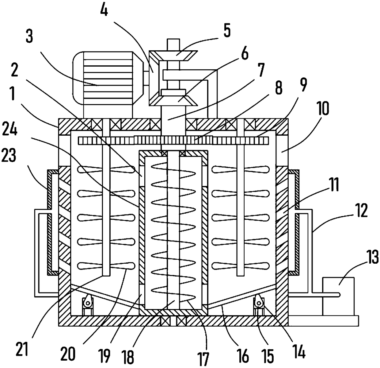
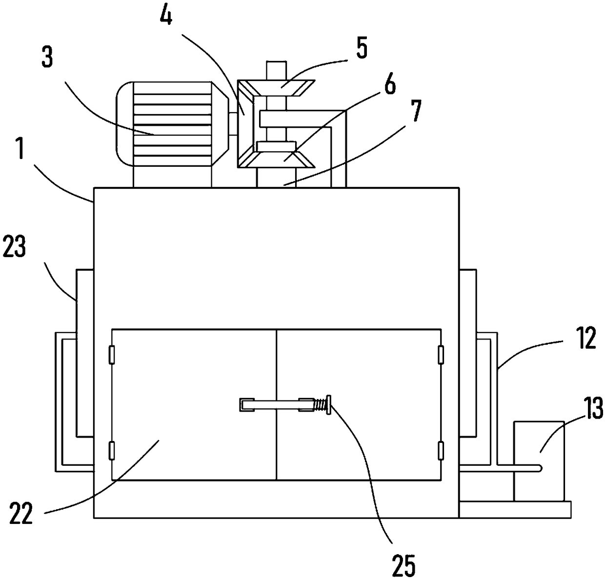
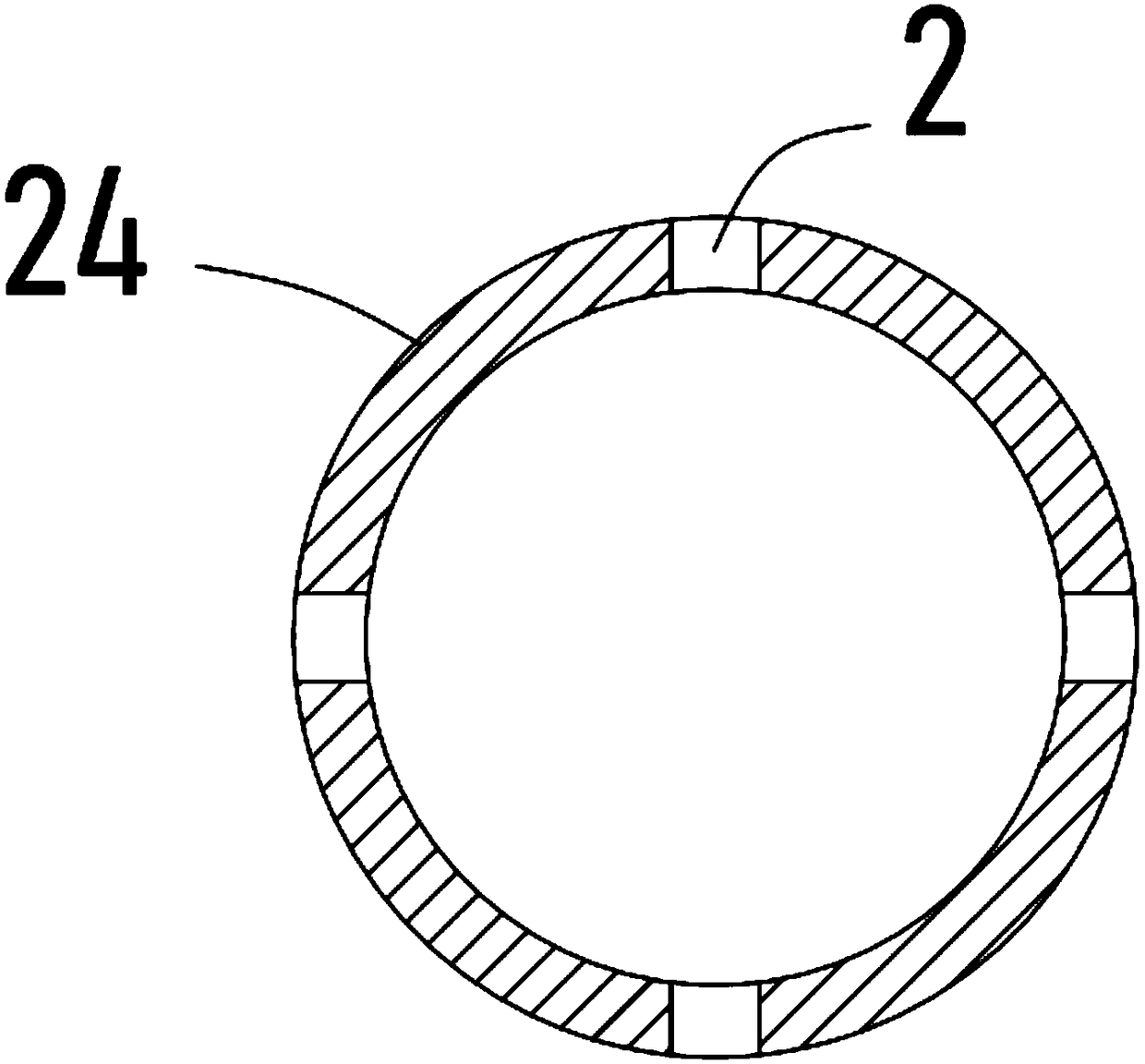
[0020] see Figure 1-3 , a biomass fuel drying device, comprising a drying box 1 and a hot air blower 13 communicating with the inside, a driving motor 3 is fixedly installed on the top of the drying box 1, and a driving bevel gear 4 is fixedly installed on the output shaft of the driving motor 3 coaxially On the drying box 1, the rotary type is vertically provided with a transmission sleeve 7, and the transmission sleeve 7 is sleeved with a driven bevel gear II6 that is meshed with the driving bevel gear 4, and the lower end of the transmission sleeve 7 is fixed with a lifting sleeve 24 , the drive motor 3 drives the driving bevel gear 4 to rotate, and the driving bevel gear 4 drives the driven bevel gear II6 to rotate through the driven bevel gear II6 meshed with it, thereby realizing the rotation of the lifting sleeve 24.

[0021] The lifting sleeve 24 is rotatably vertically provided with a lifting shaft 18 that runs through the lifting sleeve 24. The surface of the liftin...

Embodiment 2

[0026] On the basis of Embodiment 1, in addition, the driving gear 8 is sheathed and fixed on the surface of the transmission sleeve 7, and two dispersing shafts 21 are arranged vertically in a rotating manner in the drying box 1, and the driving gear 8 is sheathed and fixed on the dispersing shaft 21. 8 meshed driven gears 9, and several dispersing blades 20 are evenly fixed on the surface of the dispersing shaft 21.

[0027] The rotation of the transmission sleeve 7 drives the driving gear 8 to rotate, and the driving gear 8 drives the dispersing shaft 21 to rotate through the driven gear 9 meshed with it, and the dispersing shaft 21 drives the dispersing blade 20 to rotate to realize the rotation and dispersion of the biomass fuel. Further promotes the dispersion of fuel and improves the drying rate.

[0028] Further, an elastic material guide plate 16 is obliquely fixed in the drying box 1, one end of the elastic material guide plate 16 is fixed on the inner side wall of t...


PUM


Abstract

The invention discloses a biomass fuel drying device, and relates to the technical field of biological fuel treatment. The biomass fuel drying device comprises a drying box and a hot fan communicatedwith the interior of the drying box, the top of the drying box is fixedly provided with a driving motor, an output shaft of the driving motor is coaxially and fixedly provided with a driving bevel gear, a driven bevel gear I meshed with the driving bevel gear is fixed on the surface of a lifting rotating shaft, spiral blades positioned in a lifting sleeve are fixed on the surface of the lifting rotating shaft, a plurality of discharge ports are formed in the upper side wall of the lifting sleeve, and a plurality of feeding ports are formed in the lower side wall of the lifting sleeve. According to the biomass fuel drying device, the rotating shaft drives the spiral blades to rotate, the rotating spiral direction of the biomass fuel is improved upwards, the biomass fuel is discharged from the discharging port to be scattered by the dispersing blades in a rotating mode, the full-dispersion effect of the fuel is realized, the full contact of the hot air is realized, the fuel can be circularly lifted, fell and scattered, and the drying process is more efficient and thorough.

Description

technical field [0001] The invention relates to the technical field of bioengineering, in particular to a biomass fuel drying device. Background technique [0002] The development of new energy has become the focus of global attention, and the development of biomass renewable new energy has become a hot spot of concern from all walks of life. Biomass fuels such as various crop straws and forest wastes have not been effectively utilized for a long time. In recent years, due to The shortage of energy resources and the protection of the ecological environment have become increasingly prominent, and the development of solid biomass briquettes has attracted people's attention. [0003] In the production process of biomass pellet fuel, the drying of biomass pellet fuel is extremely important. If the biomass pellet fuel is not fully dried, it will easily agglomerate. The current drying device is only for heating treatment, but the biomass The particle fuel has a high degree of acc...

Claims


Application Information

Patent Timeline
IPC IPC(8): F26B17/22F26B17/16F26B21/00F26B25/04
CPCF26B17/16F26B17/22F26B21/004F26B25/04F26B2200/02
Inventor 李博文
Owner 郑州韦尔特生物科技有限公司
Why Eureka
Try Eureka