Tool for steering disassembly and bogie disassembling method
A bogie and machine tool technology, which is applied in the direction of manufacturing tools, metal processing, metal processing equipment, etc., can solve the problems of dismantling and dismantling load-bearing springs, wounding people, narrow operating space, and high working intensity.
- Summary
- Abstract
- Description
- Claims
- Application Information
AI Technical Summary
Problems solved by technology
Method used
Image
Examples
Embodiment 1
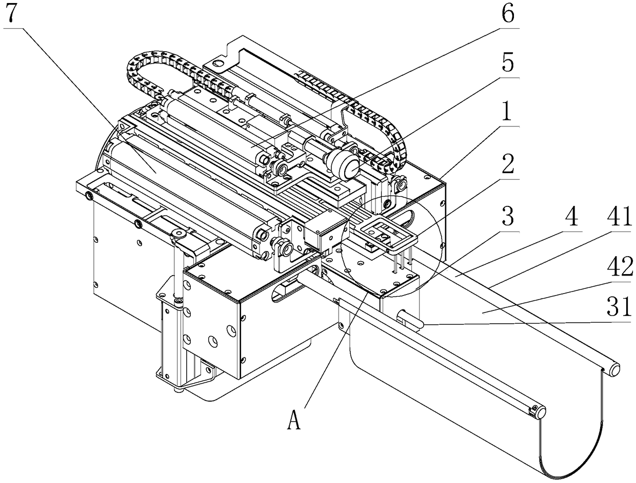
[0053] Such as Figure 1 to Figure 3 As shown, a bogie dismantling tool includes a tool frame 1 and a clamping device installed on the tool frame 1, and the clamping device includes a pull rod assembly 2 and a support member 4;
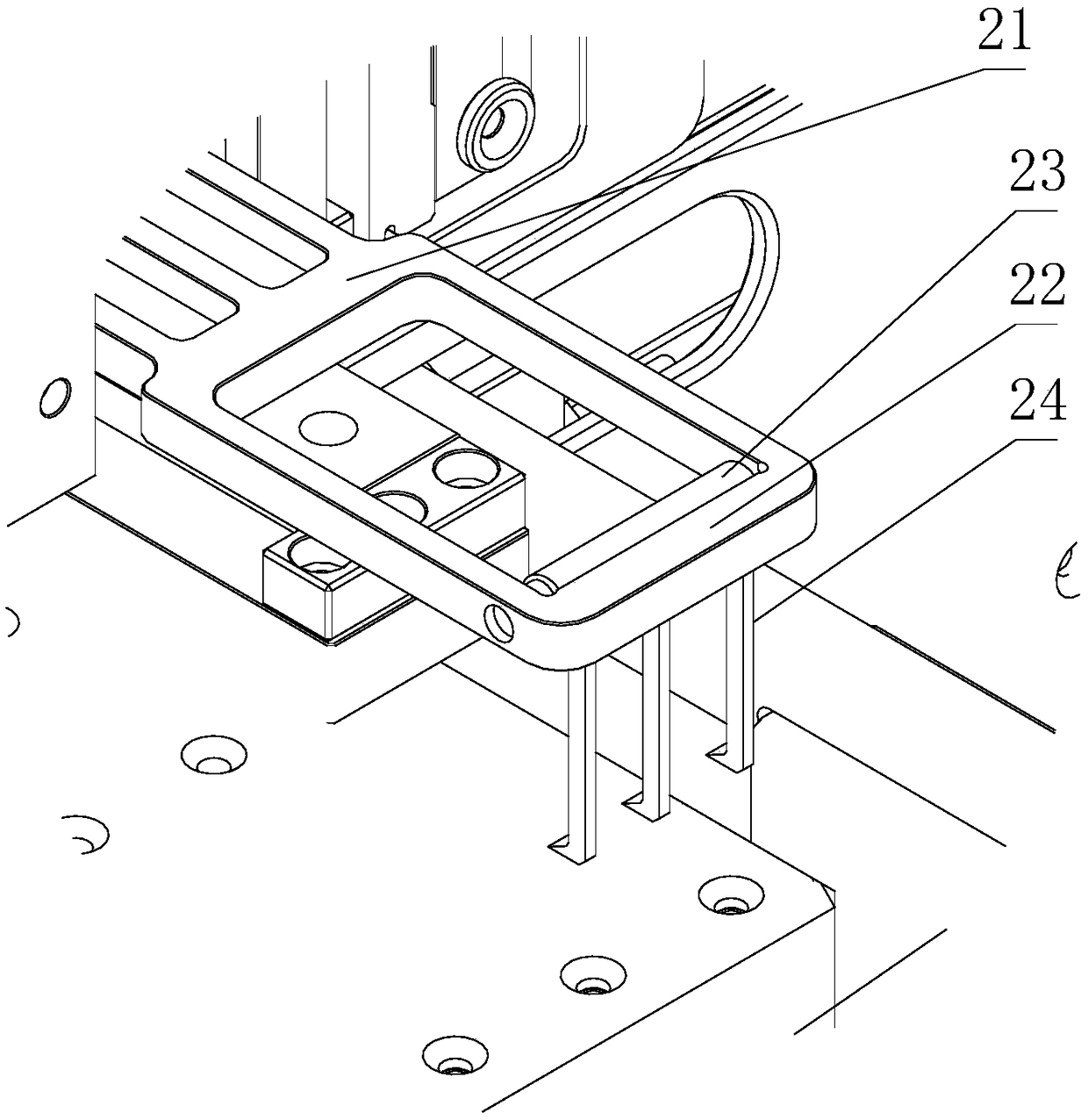
[0054] The tie rod assembly 2 includes a tie rod body 21, which is a cantilever beam-like structure protruding from the tool frame 1, and is also installed on the free end of the tie rod body 21 for applying tension to parts on the bogie. grabbing mechanism;
[0055] The pull rod body 21 is a telescopic rod that is telescopic relative to the tool frame 1;
[0056] The grasping mechanism includes a rotating shaft 23 and a gear lever 24 connected to the rotating shaft 23, one end of the gear lever 24 is fixed on the side of the rotating shaft 23;
[0057]Described rotating shaft 23 is hinged on the pull rod body 21, and the free end of described pull rod body 21 is also provided with flanging 22, and described rotating shaft 23 is adjacent to flanging...
Embodiment 2
[0066] Such as Figure 1 to Figure 3 As shown, this embodiment is further limited on the basis of Embodiment 1: as a specific implementation form of the support member 4, it is set as follows: the support member 4 includes two cantilever rods 41 protruding from the tool frame 1, and also includes a pocket Body 42, the pocket body 42 is a flexible material, one end of the pocket body 42 is fixed on one of the cantilever bars 41, and the other end of the pocket body 42 is fixed on another cantilever bar 41;
[0067] The middle part of the pocket body 42 falls down to form a pocket-shaped space for constraining the parts on the support member 4;
[0068] The supporting member 4 also includes a third driving mechanism, which is used to change the distance between the two cantilever rods 41 ;
[0069] The grabbing mechanism is located directly above the pocket-shaped space. In this solution, the pull rod assembly 2 provides pulling force for the spring to fall. Under the above pu...
Embodiment 3
[0086] This embodiment provides a bogie dismantling method, using the bogie dismantling tool provided by any one of the above embodiments to disassemble the parts on the bogie, the parts include load springs and Shock springs, including the following steps in sequence:
[0087] S1. Drive the pull rod body 21 so that the pull rod body 21 extends into the gap above the part. When the shift rod 24 contacts the part, the shift rod 24 rotates around the rotating shaft 23 so that the pull rod body 21 can continue to extend in;
[0088] When the free end of the gear lever 24 enters the central area of the part, the gear lever 24 drives the rotating shaft 23 to reverse automatically under gravity;
[0089] S2. Drive the pull rod body 21 back. When the gear rod 24 acts on the surface of the part, the folded edge 22 hinders the further rotation of the gear rod 24. At this time, the gear rod 24 applies a pulling force to the part, so that the part is dumped on said support surface;
...
PUM
 Abstract
Description
Claims
Application Information
 - R&D
- Intellectual Property
- Life Sciences
- Materials
- Tech Scout
- Unparalleled Data Quality
- Higher Quality Content
- 60% Fewer Hallucinations
Browse by: Latest US Patents, China's latest patents, Technical Efficacy Thesaurus, Application Domain, Technology Topic, Popular Technical Reports.
© 2025 PatSnap. All rights reserved.Legal|Privacy policy|Modern Slavery Act Transparency Statement|Sitemap|About US| Contact US: help@patsnap.com


