
Light-condensing-type self-cleaning road reflecting mirror

A mirror and self-cleaning technology, applied in the field of municipal transportation, can solve the problems of blurred mirror surface, decreased mirror life, poor control of cleaning cycle, etc., to achieve the effect of improving the heat collection effect

Active Publication Date: 2019-03-15
HANGZHOU ZHUILIE TECH
View PDF6 Cites 13 Cited by
  • Summary
  • Abstract
  • Description
  • Claims
  • Application Information

AI Technical Summary

Problems solved by technology

Since the road reflectors are installed on the side of the road, during use, the surface of the reflectors is prone to dust accumulation, causing the surface of the reflectors to be blurred and affecting the driver's observation. Since the road sections where each reflector is installed are different, the degree of dust accumulation varies. The cycle is not easy to control. In addition, since the reflectors are scattered in various sections along the road, it is difficult for sanitation personnel to clean the surface of the reflectors in time. The dangers of driving on the road

Method used


Image

  • Light-condensing-type self-cleaning road reflecting mirror
  • Light-condensing-type self-cleaning road reflecting mirror
  • Light-condensing-type self-cleaning road reflecting mirror

Examples


Embodiment 1

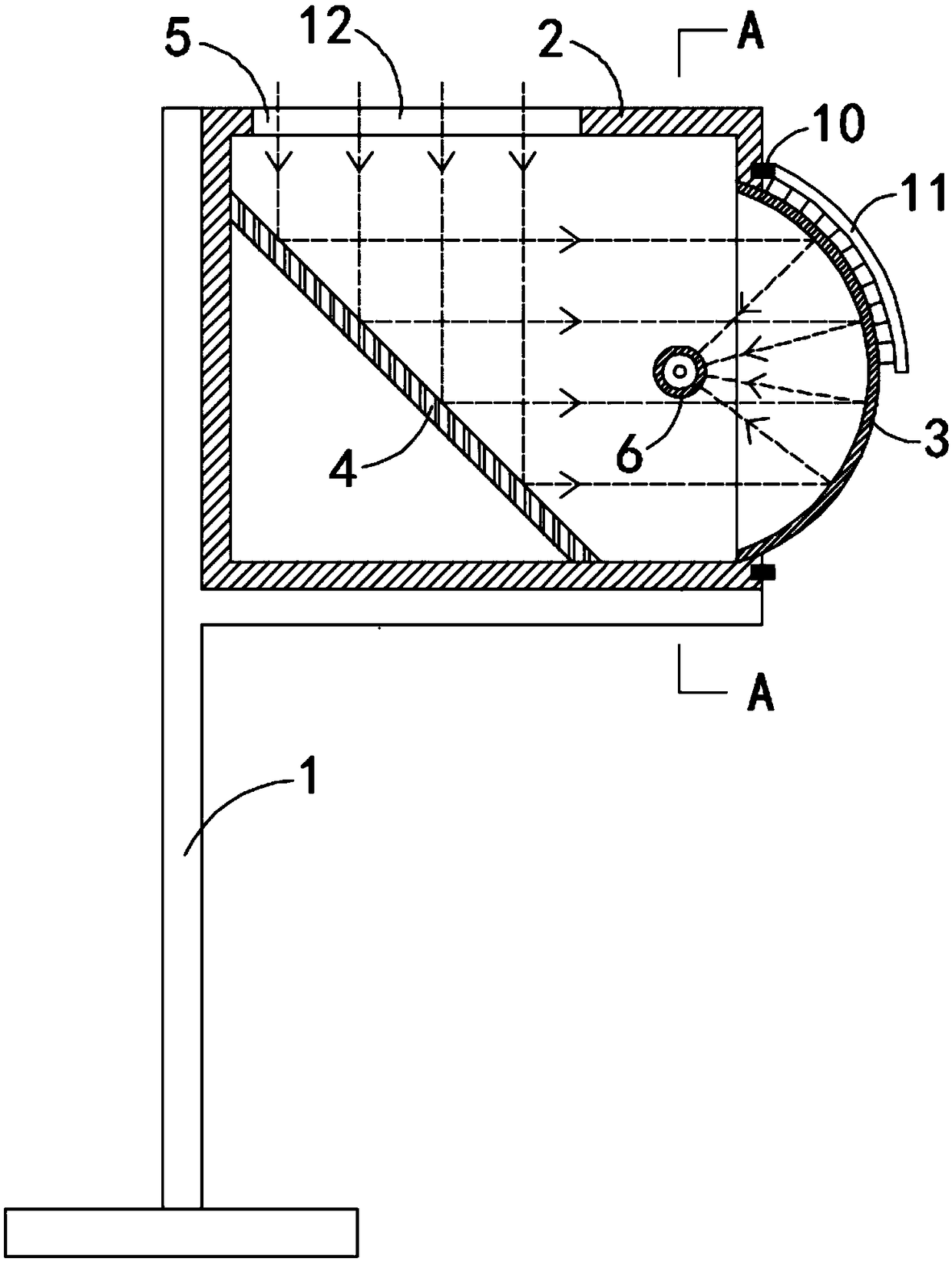
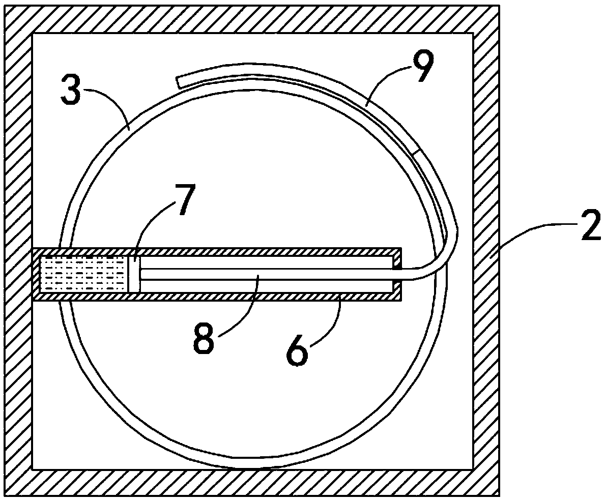
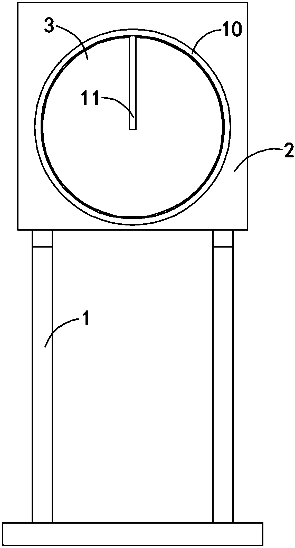
[0018] Such as Figure 1-3 As shown, a concentrating self-cleaning road reflector includes a bracket 1, the upper end of the bracket 1 is fixedly connected with a housing 2, the side wall of the housing 2 is provided with an opening, and a convex reflector 3 is fixedly connected in the opening, The housing 2 is fixedly connected with a planar reflector 4 which is arranged obliquely. The plane reflector 4 forms an angle of 45 degrees with the inner bottom surface of the housing 2 and can refract the vertical light into a horizontal light. The upper side wall of the housing 2 is provided with There is a light inlet 5, and a reflective layer is provided on the concave surface of the convex reflector 3. By setting the reflective layer, the concave surface of the convex reflector 3 forms a concave reflector. The housing 2 is fixedly connected with a liquid storage cylinder 6 arranged horizontally. The liquid storage cylinder 6 can be made of a metal with good thermal conductivity s...

Embodiment 2

[0022] Such as Figure 4 As shown, the difference between this embodiment and Embodiment 1 is that the middle part of the transparent plate 12 protrudes upwards to form a hemisphere.

[0023] In this embodiment, by setting the transparent plate 12 into a hemispherical shape that protrudes upwards, since the transparent plate 12 is higher than the upper part of the housing 2, not only the light receiving rate of the transparent plate 12 can be improved, but also the refraction of light (light refraction) can be used. route such as Figure 4 Shown by the dotted arrow in the middle), improve the heat collection effect, and can avoid the situation that sundries such as fallen leaves fall on the transparent plate 12 and affect the light concentration.


PUM


Abstract

The invention belongs to the field of municipal transportation, and particularly relates to a light-condensing-type self-cleaning road reflecting mirror. The light-condensing-type self-cleaning road reflecting mirror comprises a bracket, a shell is fixedly connected to the upper end of the bracket, the side wall of the shell is provided with an opening, a convex-surface reflecting mirror body is fixedly connected into the opening, an inclined planar reflecting mirror body is fixedly connected into the shell, and the included angle between the planar reflecting mirror body and the inner bottomsurface of the shell is 45 degrees; the upper side wall of the shell is provided with a light inlet, a reflecting layer is arranged at the concave surface of the convex-surface reflecting mirror body,a horizontal liquid storage cylinder is fixedly connected into the shell, the axis of the liquid storage cylinder penetrates through a focal point of the concave surface of the convex-surface reflecting mirror body, a piston block is sealedly and slidingly connected into the liquid storage cylinder, a closed space formed by the piston block and the liquid storage cylinder is filled with evaporating liquid, a transmission strip is fixedly connected to the other side wall of the piston block, and the inner side wall of the shell is provided with an arc sliding groove matched with the transmission strip. The light-condensing-type self-cleaning road reflecting mirror does not need to be driven with power, solar energy is fully utilized for cleaning the reflecting mirror, the energy is saved,and the environment is protected.

Description

technical field [0001] The invention belongs to the field of municipal transportation, in particular to a light-condensing self-cleaning road reflector. Background technique [0002] The road reflector is a kind of convex mirror, which is usually installed at the corner of the winding road, so that the driver can observe the information of the oncoming vehicle. Since the road reflectors are installed on the side of the road, during use, the surface of the reflector is prone to dust accumulation, causing the surface of the reflector to be blurred and affecting the driver's observation. Since the road sections where each reflector is installed are different, the degree of dust accumulation varies. The cycle is not easy to control. In addition, since the reflectors are scattered in various sections along the road, it is difficult for sanitation personnel to clean the surface of the reflectors in time. The danger of driving on the road. [0003] Therefore, we propose a concent...

Claims


Application Information

Patent Timeline
Patent Type & Authority Applications(China)
IPC IPC(8): E01F9/619
CPCE01F9/619
Inventor 余杰
Owner HANGZHOU ZHUILIE TECH
Learn More