Supercharge Your Innovation With Domain-Expert AI Agents!

Stationary waste cleaner

一种清污机、固定式的技术,应用在移土机/挖土机、水利工程、人工水道等方向,能够解决清污机无法完全保证污物输送至水流外部、清污范围有限、实用性降低等问题,达到增加清污范围、方便处理、提高实用性的效果

Active Publication Date: 2019-03-15
JIANGSU AGCO SOLID WASTE TREATMENT CO LTD
View PDF4 Cites 0 Cited by
  • Summary
  • Abstract
  • Description
  • Claims
  • Application Information

AI Technical Summary

Problems solved by technology

[0003] Sewage cleaning machines are usually divided into fixed and mobile types. Compared with mobile cleaning machines, fixed cleaning machines have a fixed position of the rake bucket in the horizontal direction, so that the rake bucket can only clean water within a limited range. The cleaning operation is carried out, so that the scope of cleaning is very limited. Not only that, because the existing cleaning device uses a rake bucket, there are gaps between the rake teeth of the rake bucket, resulting in some Smaller debris is easy to fall from between the rake teeth, so that the cleaning machine cannot fully ensure that the dirt captured in the rake bucket is transported to the outside of the water flow, resulting in a reduction in the practicability of the equipment

Method used


Image

  • Stationary waste cleaner
  • Stationary waste cleaner
  • Stationary waste cleaner

Examples


Embodiment Construction

[0031] The present invention is described in further detail now in conjunction with accompanying drawing. These drawings are all simplified schematic diagrams, which only illustrate the basic structure of the present invention in a schematic manner, so they only show the configurations related to the present invention.

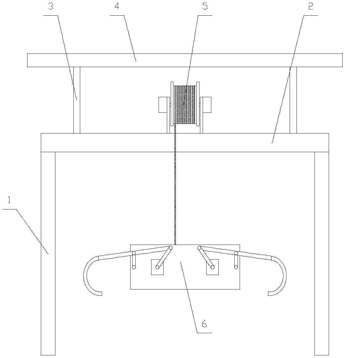
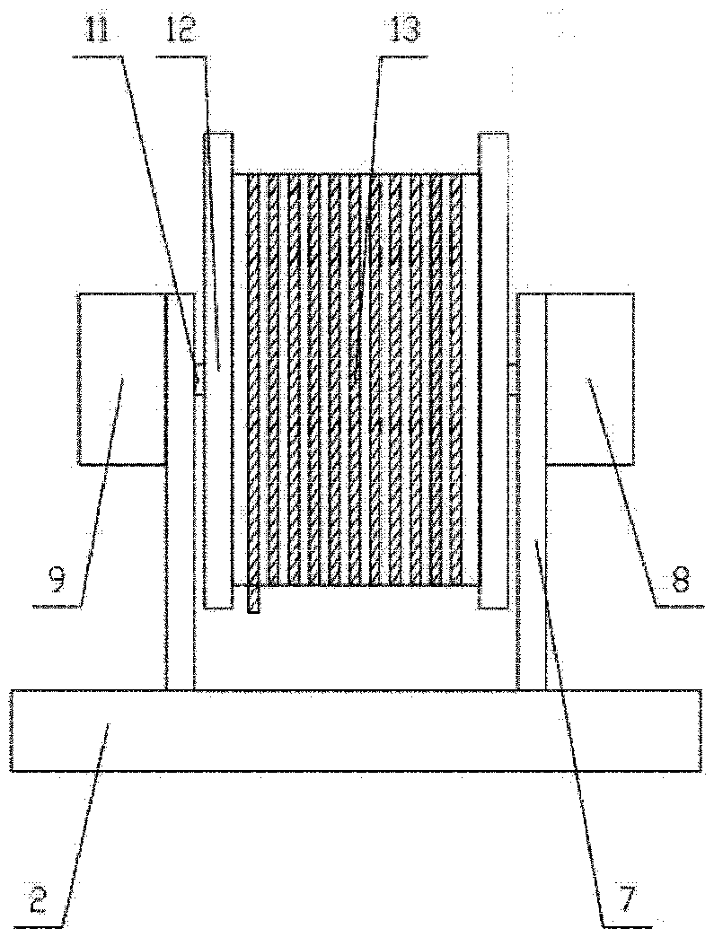
[0032] Such as Figure 1-Figure 6 As shown, an intelligent fixed cleaning machine applied to hydroelectric power generation projects includes a crossbar 2, a lifting mechanism 5, a cleaning mechanism 6 and two pillars 1, and the crossbar 2 is erected on the top of the pillar 1. The cleaning mechanism 6 is arranged between the two pillars 1, and the lifting mechanism 5 is arranged above the cross bar 2 and connected with the cleaning mechanism 6 in transmission;

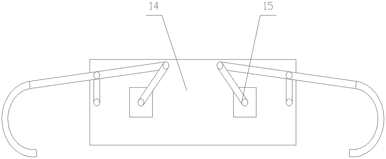
[0033] The decontamination mechanism 6 comprises a decontamination box 14 and two extension units 15, the decontamination box 14 comprises a top plate 21, a first side plate 22, a second side plate 2...


PUM


Abstract

The invention relates to a stationary waste cleaner which includes a crossbar, a lifting mechanism, a waste cleaning mechanism, and two supports. The waste cleaning mechanism includes a waste cleaningbox and two extension units, and the waste cleaning box includes a top plate, a first side plate, a second side plate, a shovel foot and a drive mechanism. In order to facilitate the measurement of the distance between the waste cleaning mechanism and the bottom of the water flow, a distance detecting unit is arranged on a side of the second side plate away from the first side plate. The distancedetecting unit includes a sleeve, a sliding rod, and a weight block. The sleeve is fixed on the second side plate, the top end of the sliding rod is arranged in the sleeve, the bottom end of the sliding rod is fixedly connected with the weight block, a pressure sensor, a spring and a connecting plate are arranged in the sleeve, the pressure sensor is fixed on the top end of the sleeve, the pressure sensor is connected with the connecting plate through the spring, and the connecting plate is fixed on the top end of the sliding rod. The invention improves the cleaning efficiency, increases thecleaning range and improves the practicability of the equipment.

Description

[0001] The patent application of the present invention is a divisional application with the application number: 2017101323808. The filing date of the original application is: 2017-03-07. The name of the invention is: an intelligent stationary cleaning machine for hydroelectric power generation projects. technical field [0002] The invention relates to the field of hydroelectric power generation equipment, in particular to a fixed cleaning machine. Background technique [0003] Sewage cleaning machines are usually divided into fixed and mobile types. Compared with mobile cleaning machines, fixed cleaning machines have a fixed position of the rake bucket in the horizontal direction, so that the rake bucket can only clean water within a limited range. The cleaning operation is carried out, so that the scope of cleaning is very limited. Not only that, because the existing cleaning device uses a rake bucket, there are gaps between the rake teeth of the rake bucket, resulting in s...

Claims


Application Information

Patent Timeline
Patent Type & Authority Applications(China)
IPC IPC(8): E02B5/08E02F5/28
CPCE02B5/085E02F5/28
Inventor 不公告发明人
Owner JIANGSU AGCO SOLID WASTE TREATMENT CO LTD
Features
  • R&D
  • Intellectual Property
  • Life Sciences
  • Materials
  • Tech Scout
  • Unparalleled Data Quality
  • Higher Quality Content
  • 60% Fewer Hallucinations
Learn More