Gas tube joint of gas cooker

A gas pipe joint, gas stove technology, applied in the direction of pipe/pipe joint/pipe fitting, hose connection device, gas/liquid distribution and storage, etc. The effect of swinging and avoiding gas leakage

Active Publication Date: 2019-03-15
山东华尊建筑有限责任公司
View PDF5 Cites 1 Cited by
  • Summary
  • Abstract
  • Description
  • Claims
  • Application Information

AI Technical Summary

Problems solved by technology

The joints of the current gas stove trachea are composed of a trachea plus a sealing joint. At the same time, there is only a flower-shaped round grip in the middle of the sealing joint. People can only twist it with their hands when connecting the gas tank. With the help of tools, the circular grip block cannot be clamped well, and it is troublesome and cannot be tightened effectively; moreover, there is a large gap between the air pipe and the sealing joint, and the sealing joint cannot be well placed on a relatively stable centerline on, causing the sealing joint to rotate freely
To sum up, the traditional gas stove gas pipe joints cannot be tightened manually, which makes people feel painful, and it is not easy to fix the position. People do not have confidence in whether they are screwed properly, and it is easy to lock the joint and cause the danger of gas leakage. question
[0003] Therefore, there is a need to design a gas stove gas pipe joint that allows people to easily and quickly connect the gas tank while saving effort and worry, so as to avoid the danger of gas leakage caused by manual tightening or even twisting

Method used


Image

  • Gas tube joint of gas cooker
  • Gas tube joint of gas cooker
  • Gas tube joint of gas cooker

Examples


Embodiment Construction

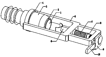
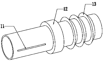
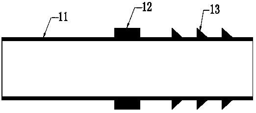
[0030] The present invention is described in further detail by specific embodiment now in conjunction with accompanying drawing:

[0031] like Figure 1 to Figure 12 As shown, a gas stove gas pipe joint, the gas stove gas pipe joint includes a gas pipe 1, a front sealing ring 2, a sealing joint 3, a middle sealing ring 4, a push rod support frame 5, a push rod 6, a spring 7, a rotating rod 8. Connecting rod 9, handle 10; the trachea 1 is cylindrical as a whole; the front sealing ring 2 is set on the front inner side of the sealing joint 3; the middle sealing ring 4 is set at the limit position of the middle sealing joint of the sealing joint 3 block place; the ejector rod support frame 5 is connected on the sealing joint 3 with a rotating shaft; the ejector rod 6 is installed in the ejector rod support frame 5; the spring 7 is installed on the ejector rod 6 and Between the rotating rods 8; the connecting rod 9 is connected to the tail end of the rotating rod 8; the handle 10 ...


PUM


Abstract

The invention discloses a gas tube joint of a gas cooker. The gas tube joint of the gas cooker comprises a gas tube, a front sealing ring, a sealing joint, a middle sealing ring, an ejector rod supporting frame, an ejector rod, a spring, a rotary rod, a connecting rod and a handle, wherein the gas tube is integrally cylindrical; the front sealing ring is arranged at the inner side in front of thesealing joint; the middle sealing ring is arranged on a sealing joint limiting block on the middle part of the sealing joint; the ejector rod supporting frame is connected on the sealing joint througha rotary shaft; the ejector rod is mounted in the ejector rod supporting frame; the spring is mounted between the ejector rod and the rotary rod; the connecting rod is connected to the tail end of the rotary rod; and the handle is connected to the tail end of the connecting rod. The gas tube joint is simple in structure, is scientific and reasonable in design, can quickly help people to connect agas tank and screw up the gas tank, improves the efficiency of accurately screwing up the gas tube joint of the gas cooker by people, and further guarantees use safety of gas.

Description

technical field [0001] The invention belongs to the technical field of gas stove accessories, in particular to a gas stove gas pipe joint. Background technique [0002] Nowadays, the living standard in our country is improving day by day, and many families have used gas stoves. Gas stoves need to be connected to a gas tank with gas before they can catch fire. The joints of the current gas stove trachea are composed of a trachea plus a sealing joint. At the same time, there is only a flower-shaped round grip in the middle of the sealing joint. People can only twist it with their hands when connecting the gas tank. With the help of tools, the circular grip block cannot be clamped well, and it is troublesome and cannot be tightened effectively; moreover, there is a large gap between the air pipe and the sealing joint, and the sealing joint cannot be well placed on a relatively stable centerline on, causing the seal joint to rotate freely. To sum up, the traditional gas stove...

Claims


Application Information

Patent Timeline
Patent Type & Authority Applications(China)
IPC IPC(8): F16L33/00F17C13/00
CPCF16L33/00F17C13/00F17C2205/0364F17C2270/0745
Inventor 不公告发明人
Owner 山东华尊建筑有限责任公司
Why Eureka
Try Eureka