Checking device
An inspection device, a circular technology, applied to measuring devices, instruments, and electromagnetic wave detection, etc., can solve the problems of low inspection accuracy and inability to obtain inspection areas at the same time, and achieve the effect of high-precision inspection and high-speed inspection
- Summary
- Abstract
- Description
- Claims
- Application Information
AI Technical Summary
Problems solved by technology
Method used
Image
Examples
Embodiment approach 1
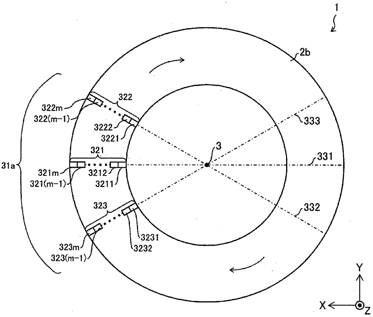
[0054] image 3 It is a figure which shows the structure of the electromagnetic wave receiving part 31a (n electromagnetic wave receiving regions) which concerns on Embodiment 1 of this invention, and shows the planar state of the circular outer surface 2b. The electromagnetic wave receiving unit 31 a has three electromagnetic wave receiving regions 321 to 323 .
[0055] The electromagnetic wave receiving area 321 has m small areas composed of a small area 3211 , a small area 3212 , . . . , a small area 321(m−1), and a small area 321m. And, small area 3211, small area 3212, ..., small area 321 (m-1) and small area 321m are observed in plan view of circular outer surface 2b, and the diameter 331 of the circle constituting the outer shape of circular outer surface 2b They are arranged side by side sequentially from the center 3 sides toward the edge side of the circle.
[0056] The electromagnetic wave receiving area 322 has m small areas composed of a small area 3221 , a smal...
Embodiment approach 2
[0062] Figure 4 It is a figure which shows the structure of the electromagnetic wave receiving part 31b (n electromagnetic wave receiving regions) which concerns on Embodiment 2 of this invention, and shows the planar state of the circular outer surface 2b.
[0063] The electromagnetic wave receiving unit 31b has the same configuration as the electromagnetic wave receiving unit 31a except for the points described below. In addition, the following "circumferential direction" means the direction along the circumference of the circle which comprises the outer shape of the circular outer surface 2b (and the circular outer surface 2a).
[0064] In the electromagnetic wave receiving area 321, the size in the circumferential direction of the small area 3212 is larger than the size in the circumferential direction of the small area 3211, ..., the size in the circumferential direction of the small area 321m is larger than the size in the circumferential direction of the small area 321...
PUM
 Abstract
Description
Claims
Application Information
 - R&D
- Intellectual Property
- Life Sciences
- Materials
- Tech Scout
- Unparalleled Data Quality
- Higher Quality Content
- 60% Fewer Hallucinations
Browse by: Latest US Patents, China's latest patents, Technical Efficacy Thesaurus, Application Domain, Technology Topic, Popular Technical Reports.
© 2025 PatSnap. All rights reserved.Legal|Privacy policy|Modern Slavery Act Transparency Statement|Sitemap|About US| Contact US: help@patsnap.com


