

Bottom backlight device with view angle deflection function
A technology of backlight device and angle of view, which is applied in optics, nonlinear optics, instruments, etc., can solve the problems of reduced light efficiency of backlight and achieve full utilization
- Summary
- Abstract
- Description
- Claims
- Application Information
AI Technical Summary
Problems solved by technology
Method used
Image

Examples
Embodiment Construction
[0027] Specific embodiments of the present invention will be described in detail below in conjunction with the accompanying drawings. It should be understood that the specific embodiments described here are only used to illustrate and explain the present invention, and are not intended to limit the present invention.
[0028] In the present invention, in the absence of a contrary statement, the orientation words included in the term, such as "upper, lower, inner, outer", etc., only represent the orientation of the term in the normal use state, or are understood by those skilled in the art. colloquial term and should not be construed as a limitation of the term.
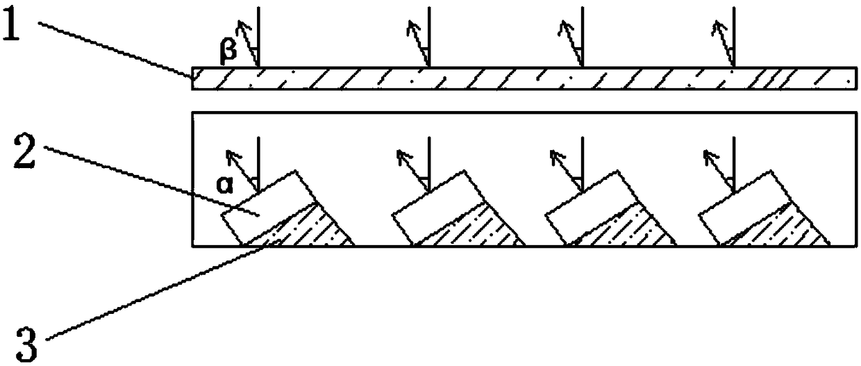
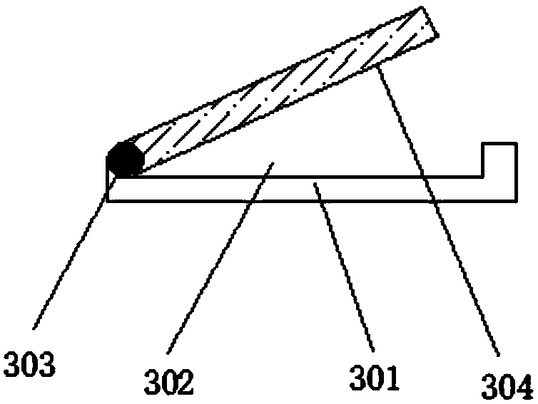
[0029] Such as figure 1 and figure 2 As shown, the present invention provides a bottom backlight device with viewing angle deflection, and the bottom backlight device with viewing angle deflection includes: LED lamp 2, support body 3 and diffuser plate 1; multiple LED lamps 2 are arranged at equal intervals , and ...
PUM
 Abstract
Description
Claims
Application Information