A Method and System for Atmospheric Correction of Visible Light Remote Sensing Satellite Images

A remote sensing satellite and atmospheric correction technology, applied in the field of remote sensing satellites, can solve problems such as high measurement costs, affecting the quantitative application of visible light remote sensing satellite images, and inability to meet large-scale quantification, achieving the effect of strong engineering application significance.

Active Publication Date: 2020-12-22
CHINA CENT FOR RESOURCES SATELLITE DATA & APPL
View PDF6 Cites 0 Cited by
  • Summary
  • Abstract
  • Description
  • Claims
  • Application Information

AI Technical Summary

Problems solved by technology

Among them, the method based on the ground linear regression model needs to be based on a large number of field spectral measurements of different ground objects, and the measurement cost is high and cannot meet the needs of large-scale quantification; However, in many areas, the atmospheric parameters cannot be obtained or even if the atmospheric parameters are obtained, most of the atmospheric parameters are the atmospheric parameters of the observation points. It is difficult to meet the quantitative requirements of remote sensing in large areas; Quantification is required, but it usually requires the cooperation of multiple remote sensing image bands (for example, the dark target method requires blue light band, red light band and 2.1 μm mid-wave infrared band, and the multi-angle method requires multiple angle information for each band imaging ), it is impossible to realize the atmospheric correction of single-band images or incomplete images of visible light remote sensing satellites, which seriously affects the quantitative application of visible light remote sensing satellite images

Method used


Image

  • A Method and System for Atmospheric Correction of Visible Light Remote Sensing Satellite Images
  • A Method and System for Atmospheric Correction of Visible Light Remote Sensing Satellite Images
  • A Method and System for Atmospheric Correction of Visible Light Remote Sensing Satellite Images

Examples


Embodiment Construction

[0051] In order to make the object, technical solution and advantages of the present invention clearer, the embodiments disclosed in the present invention will be further described in detail below in conjunction with the accompanying drawings.

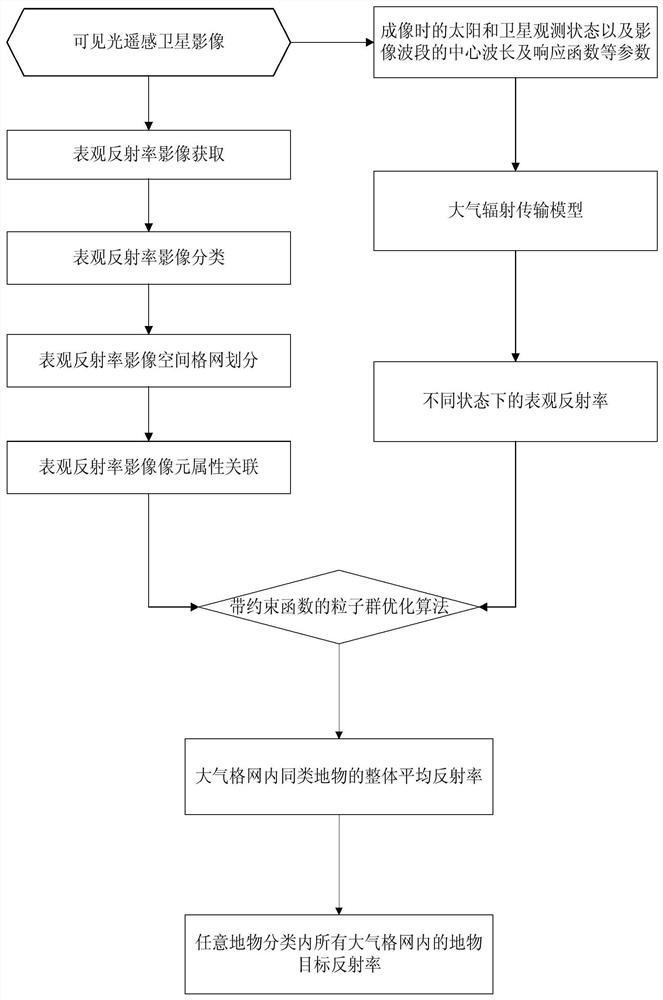
[0052] refer to figure 1 , shows a flow chart of the steps of a method for atmospheric correction of visible light remote sensing satellite images in an embodiment of the present invention. In this embodiment, the atmospheric correction method of the visible light remote sensing satellite image includes:

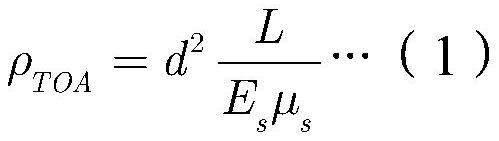
[0053] Step 101, converting the gray value image of the visible light remote sensing satellite into an apparent radiance image to obtain an apparent reflectance image.

[0054] In this embodiment, the gray value image of the visible light remote sensing satellite can be converted into an apparent radiance image according to the absolute radiation calibration coefficient and absolute radiation calibration calculation formula provided...


PUM


Abstract

The invention discloses an atmospheric correction method and system for a visible light remote sensing satellite image. The method includes: converting the gray value image of the visible light remote sensing satellite into an apparent radiance image to obtain an apparent reflectance image; The image is classified to obtain the classified image; the atmospheric reflectance image is divided into atmospheric grids according to the atmospheric grid interval to obtain the spatial grid division image; the spatial overlay analysis is carried out on the classification image and the spatial grid division image to obtain The classification attribute, spatial grid attribute, pixel apparent reflectance value and corresponding position association of each pixel in the image; establish an image atmospheric correction model, and perform image atmospheric correction and inversion based on the image atmospheric correction model to determine any ground object The object reflectance in all atmospheric grids in the classification. The invention solves the problem of atmospheric correction in any band of visible light remote sensing satellite images.

Description

technical field [0001] The invention belongs to the technical field of remote sensing satellites, in particular to an atmospheric correction method and system for visible light remote sensing satellite images. Background technique [0002] The atmosphere is the necessary medium for remote sensing imaging to detect, collect and transmit the radiation of ground objects. The radiation of ground objects will have a series of interactions with the atmosphere during the transmission process of the atmosphere, resulting in changes in radiation transmission characteristics, making the information recorded in remote sensing images It cannot truly reflect the radiation information of ground objects, which has a great impact on the quality of remote sensing images and the interpretation and quantitative analysis of remote sensing images. Therefore, to eliminate the influence of the atmosphere on the radiation of ground objects and restore the true colors of ground objects becomes An es...

Claims


Application Information

Patent Timeline
Patent Type & Authority Patents(China)
IPC IPC(8): G06K9/00G06T5/00
CPCG06T5/001G06T2207/10032G06V20/13
Inventor 王爱春闵祥军潘志强赵航韩启金李晓进
Owner CHINA CENT FOR RESOURCES SATELLITE DATA & APPL
Why Eureka
Try Eureka