Non-polarized low-voltage circuit breaker

A low-voltage circuit breaker, non-polarity technology, which is applied in the direction of circuit breaker components, circuit breaker contacts, protective switch operation/release mechanism, etc., can solve the problems of inability to achieve reliable arc ignition and arc extinguishing effects, and achieve favorable arc The effect of extinguishing and short breaking time

Inactive Publication Date: 2019-03-15
XIAMEN ANDAXING ELECTRIC GRP CO LTD
View PDF6 Cites 3 Cited by
  • Summary
  • Abstract
  • Description
  • Claims
  • Application Information

AI Technical Summary

Problems solved by technology

[0006] The purpose of the present invention is to provide a non-polar low-voltage circuit breaker to overcome the problem that the prior art cannot achieve reliable arc ignition and arc extinguishing effects, and it does not need to consider the polarity, which improves the safety of use

Method used


Image

  • Non-polarized low-voltage circuit breaker
  • Non-polarized low-voltage circuit breaker
  • Non-polarized low-voltage circuit breaker

Examples


Embodiment 1

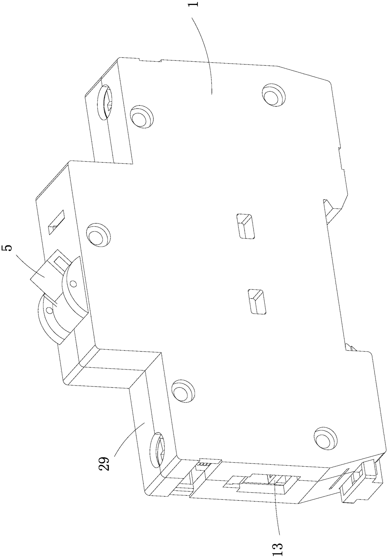
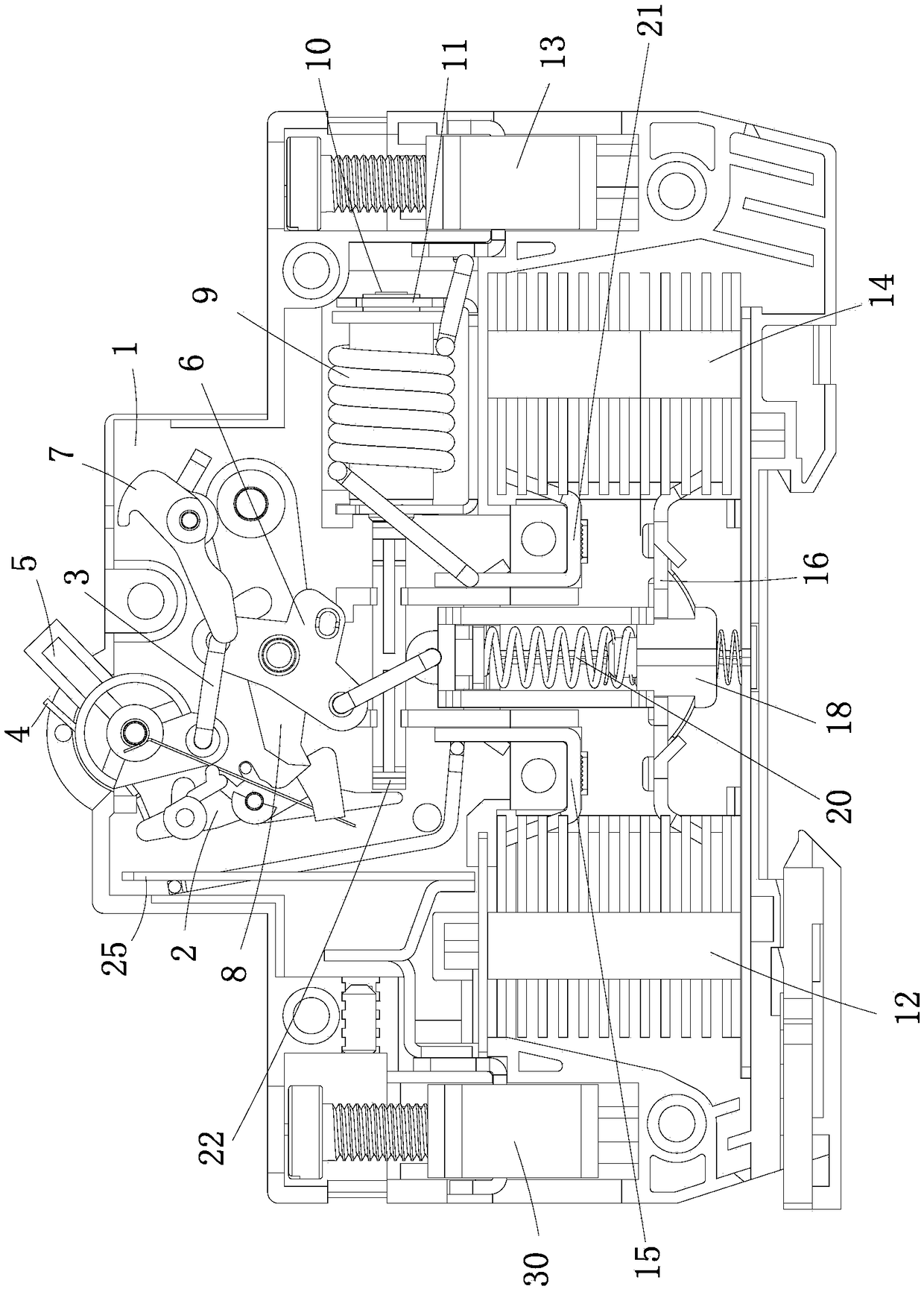
[0033] Example 1: Such as Figure 1 to Figure 6 As shown, the non-polar low-voltage circuit breaker provided by the present invention mainly includes: a plastic shell and left and right wiring clamp components placed therein, an operating mechanism, a magnetic trip system, a thermal trip system, a bridge type movable contact assembly 16, two groups Static contact assembly and two arc extinguishing chambers. The housing includes a base 1 and an upper cover 29, and all internal parts of the circuit breaker are installed based on the base 1 and the upper cover 29. Among them, the left wiring clamp assembly 30 is connected to the thermal trip system and the power supply, the right wiring clamp assembly 13 is connected to the magnetic trip system and the load, and the magnetic trip system and the thermal trip system pass through the bridge movable contact assembly 16 and the static contact assembly The closing of 15 realizes electrical connection. The bridge-type moving contact as...

Embodiment 2

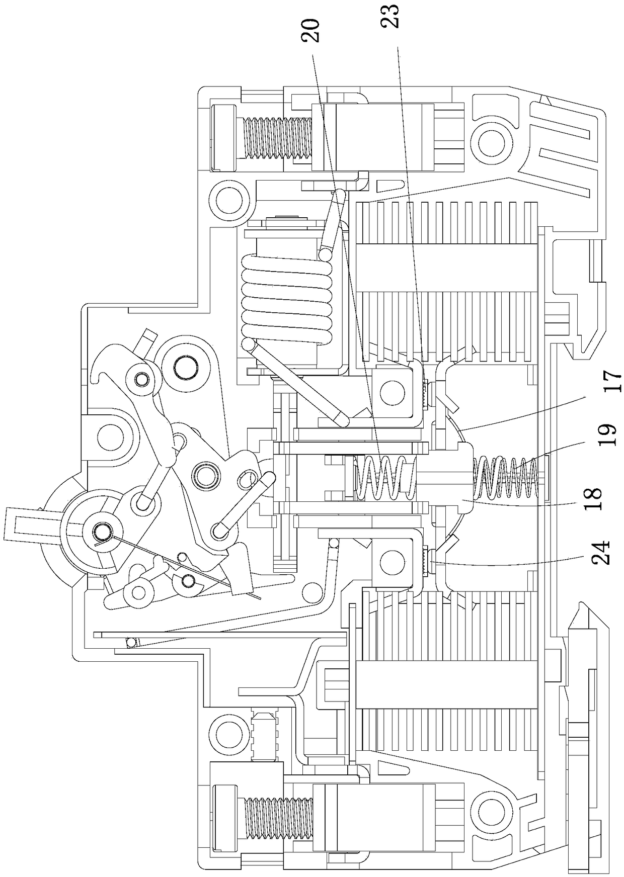
[0047] Embodiment 2: The difference between this embodiment 2 and embodiment 1 is that two springs 34 are used instead of the spring leaf 17 described in embodiment 1, such as Figure 7 with Picture 9 As shown, two springs 34 are located between the contact bridge and the moving contact bracket 18, and are respectively located below the two moving contacts. The bridge type moving contact assembly 16, the two springs 34 and the moving contact bracket 18 constitute the contact. The overtravel mechanism has better stability. Move the moving contact bracket up and drive the bridge type moving contact assembly to contact with the left and right static contact assemblies, then continue to move the contact bracket up, the moving contact bracket compresses two springs, and the two springs are bridge type moving contacts The closure of the component and the static contact component provides reliable contact pressure. The upper end of the conductive spring 19 passes through the avoidanc...


PUM


Abstract

Disclosed is a non-polarized low-voltage circuit breaker, relating to the technical field of electrical switches. The non-polarized low-voltage circuit breaker includes an operating mechanism, two static contact assemblies, a bridge type moving contact assembly and two arc extinguishing chambers. The bridge type moving contact assembly is arranged opposite to the static contact assemblies. The twostatic contact assemblies are input and output static contact assemblies. The bridge type moving contact assembly and the two static contact assemblies are cooperated to form a left moving and staticcontact fracture and a right moving and static contact fracture. The left and right moving and static contact fractures are closely adjacent to the matched arc extinguishing chambers. When a circuitis switched on and off, arc is formed between the left and right moving and static contact fractures and generated self-excited magnetic fields repel each other since the current directions of the arcare opposite to drive the arc at the left and right fractures to automatically enter the two arc extinguishing chambers to realize arc extinguishing. The circuit breaker has two switch fractures andtwo arc extinguishing chambers, the two switch fractures are connected in series, arc energy produced when the circuit is opened is born by the two fractures, and arc extinguishing is born by the twoarc extinguishing chambers, so that the circuit breaker is favorable for rapid arc extinguishing.

Description

Technical field [0001] The invention relates to the technical field of electrical switches, in particular to a non-polarity low-voltage circuit breaker. Background technique [0002] Existing low-voltage circuit breakers usually have only one switch fracture, the switch fracture is composed of a rotating movable contact and a static contact, and an arc extinguishing chamber is configured corresponding to the switch fracture. When the circuit is opened, all the arc energy is broken by this fracture and the arc is extinguished by this arc extinguishing chamber. Its arc extinguishing ability is weak. This structure limits the breaking capacity of the circuit breaker. [0003] There is a distance between the switch fracture and the arc extinguishing chamber. This distance is generally between 6 and 12mm. After the arc is generated in the circuit, it is necessary to introduce the arc into the arc extinguishing chamber through the arc ignition plate, the arc ignition piece, etc., resulti...

Claims


Application Information

Patent Timeline
Patent Type & Authority Applications(China)
IPC IPC(8): H01H73/18H01H73/04H01H71/10
CPCH01H71/10H01H73/04H01H73/18
Inventor 吴锦松薛建和韩骁勇
Owner XIAMEN ANDAXING ELECTRIC GRP CO LTD
Why Eureka
Try Eureka