Fault current transfer device for direct-current system

A fault current, DC system technology, applied in the field of DC systems, can solve the problems of large damage ratio and reduce the availability of DC circuit breakers, and achieve the effects of reducing energy absorption, improving the success rate of reclosing, and saving investment.

Inactive Publication Date: 2017-11-14
NR ELECTRIC CO LTD +1
View PDF7 Cites 1 Cited by
  • Summary
  • Abstract
  • Description
  • Claims
  • Application Information

AI Technical Summary

Problems solved by technology

However, MOV will bear huge energy in this process. From the perspective of similar engineering applications, the damage ratio of mul

Method used


Image

  • Fault current transfer device for direct-current system
  • Fault current transfer device for direct-current system
  • Fault current transfer device for direct-current system

Examples


Embodiment Construction

[0022] The technical solutions of the present invention will be described in detail below in conjunction with the accompanying drawings.

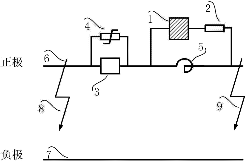
[0023] The invention provides a fault current transfer device applied in the field of DC systems, such as figure 1 As shown, the fault current transfer device is composed of a power electronic valve and a absorbing resistor;

[0024] Such as figure 1 As shown, the connection mode of the fault current transfer device is as follows: the power electronic valve 1 and the absorbing resistor 2 are connected in parallel at both ends of the smoothing reactor 5, and the relative positions of the power electronic valve 1 and the absorbing resistor 2 are not limited; Valve 1 can be a one-way valve or a two-way valve.

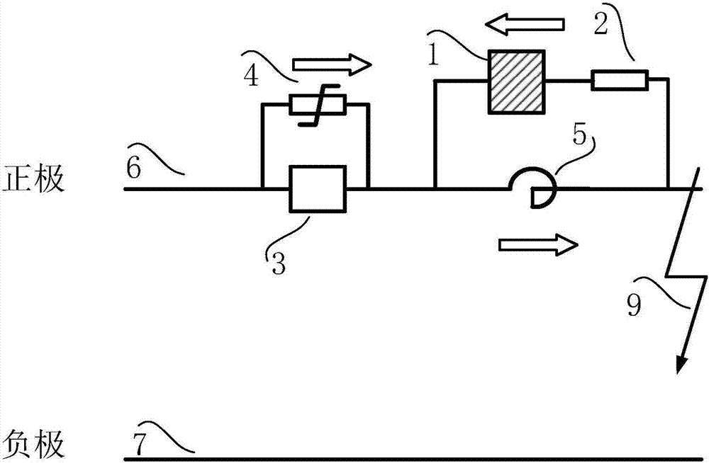
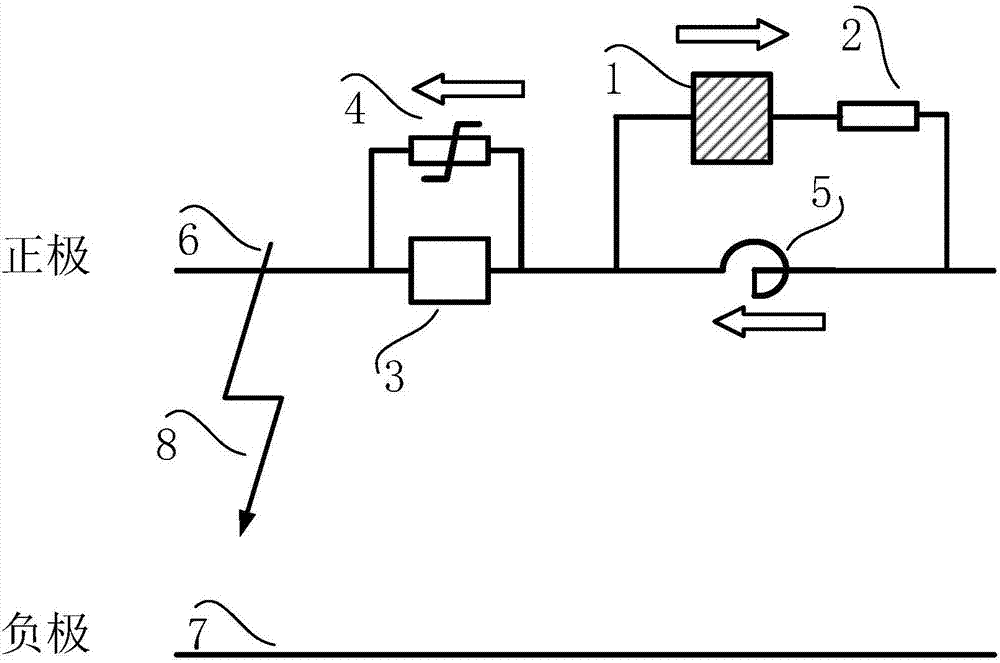
[0025] Such as figure 2 As shown, when a ground fault occurs on the outlet side 9 of the HVDC transmission system, the fault current rises with a certain slope through the smoothing reactor 5, and when the DC circuit breaker control...


PUM


Abstract

The invention discloses a fault current transfer device for a direct-current system. The fault current transfer device includes a power electronic valve and an absorption resistor; the power electronic valve and the absorption resistor are connected in series to form a first branch; and the first branch is connected in parallel at two ends of a smoothing reactor and is used for transferring fault current which appears when a grounding fault occurs on the incoming line side of a direct-current circuit breaker; and the power electronic valve can be a one-way phase valve or a two-way valve so as to realize fault current transfer at different fault points. The fault current transfer device is used for transferring the fault current of the direct-current system, improving the protection margin of the MOV of the direct-current circuit breaker and achieving rapid extinction of the fault current so as to improve the success rate of the reclosing of the direct-current system.

Description

technical field [0001] The invention belongs to the field of DC systems, in particular to a DC system fault current transfer device. Background technique [0002] The DC transmission system consists of a rectifier, a DC transmission line and an inverter, where the rectifier and the inverter are collectively referred to as a converter. From a structural point of view, HVDC transmission is an AC-DC-AC power electronic commutation circuit. Since the world's first high-voltage direct current transmission project in Gland, Sweden, was put into operation in 1954, high-voltage direct current transmission technology has developed rapidly with the rapid development of power electronics technology. In the structure of HVDC power transmission project, DC circuit breaker is one of the crucial equipment. DC circuit breakers need to break through three technical difficulties: the DC transmission current does not have a zero-crossing point, which increases the difficulty of arc extinguis...

Claims


Application Information

Patent Timeline
IPC IPC(8): H02H7/26H02H9/02
CPCH02H7/268H02H9/02
Inventor 李晓明曹冬明石巍卢宇
Owner NR ELECTRIC CO LTD
Why Eureka
Try Eureka