Retaining ring for cmp

A technology for retaining rings and polishing pads, which is applied to grinding machine tools, manufacturing tools, grinding devices, etc., can solve the problems of easy wear of retaining rings, reduce the rebound effect of pads, and improve the uniformity of polishing

Active Publication Date: 2019-03-15
APPLIED MATERIALS INC
View PDF11 Cites 4 Cited by
  • Summary
  • Abstract
  • Description
  • Claims
  • Application Information

AI Technical Summary

Problems solved by technology

However, because the retaining ring contacts the polishing pad, the retaining ring is prone to wear and occasional replacement of the retaining ring

Method used


Image

  • Retaining ring for cmp
  • Retaining ring for cmp
  • Retaining ring for cmp

Examples


Embodiment Construction

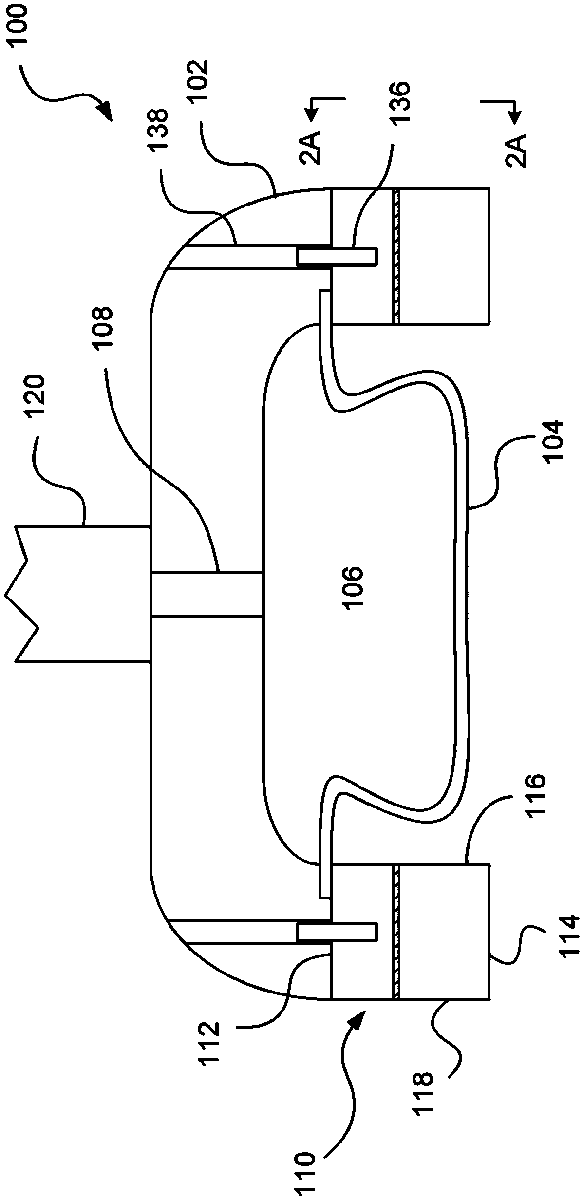
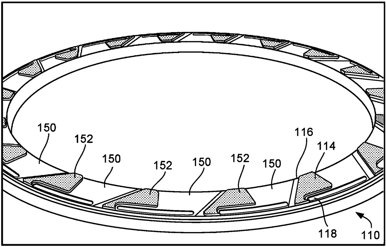
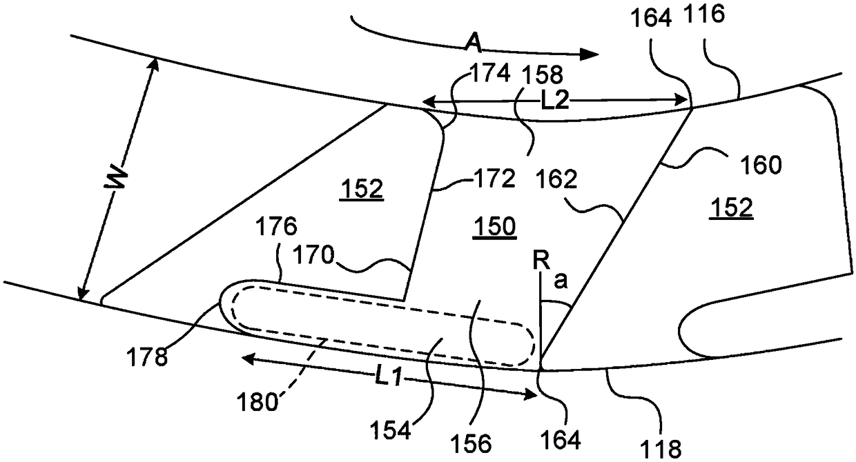
[0018] A retaining ring may be used to press against the surface of the polishing pad in the area surrounding the substrate. Specifically, the retaining ring needs to be pressed with sufficient force so that the substrate does not accidentally slide under the ring and effectively catches the substrate. The retaining ring can also be used to compress the polishing pad near the edge of the substrate and thus affect the polishing rate at the edge of the substrate. However, when the pad is compressed in this manner, the elasticity of the polishing pad, along with the relative motion between the pad and the retaining ring, can lead to a "pad springback effect," which can increase radial non-uniformity.

[0019] Two techniques can be used to reduce pad springback effects. First, by reducing the contact area of ​​the retaining ring against the polishing pad, less of the pad is squeezed and thus less of the substrate is subject to pad bounce. Second, certain shapes of contact area a...


PUM


Abstract

A retaining ring includes a generally annular body having an inner surface to constrain a substrate and a bottom surface, the bottom surface having a plurality of channels extending from an outer surface to the inner surface, and a plurality of islands separated by the channels and providing a contact area to contact a polishing pad, wherein the contact area is about 15-40% of a plan area of the bottom surface.

Description

technical field [0001] The present disclosure relates to a retaining ring of a carrier head for chemical mechanical polishing. Background technique [0002] Integrated circuits (especially silicon wafers) are usually formed on a substrate by successively depositing conductive, semiconducting or insulating layers. One fabrication step includes depositing a filler layer on a non-planar surface and planarizing the filler layer. For some applications, the filler layer is planarized until the top surface of the patterned layer is exposed. For example, a conductive filler layer may be deposited on the patterned insulating layer to fill trenches or holes in the insulating layer. After planarization, the portions of the conductive layer left between the raised patterns of the insulating layer form vias, plugs and wires that are provided between the thin film circuits on the substrate. conductive path. For other applications such as oxide polishing, the filler layer is planarized...

Claims


Application Information

Patent Timeline
Patent Type & Authority Applications(China)
IPC IPC(8): B24B37/32H01L21/687B24B37/04H01L21/306
CPCB24B37/32H01L21/68721H01L21/68735B24B37/04H01L21/30625H01L21/67092H01L21/67063
Inventor 安德鲁·J·纳甘盖斯特克里斯托弗·兴-均·李托马斯·李阿南德·N·伊耶刁杰焕波·张埃里克·S·罗丹姆李魏成吴正勋
Owner APPLIED MATERIALS INC
Why Eureka
Try Eureka