
New composite wire saw winding equipment

A composite wire and equipment technology, which is applied in the field of new composite wire saw winding equipment, can solve the problems of uncontrollable winding process and inability to set the winding gap of outer wires, so as to improve cutting efficiency and slice quality, controllable winding process, reduce The effect of rebound effect

Active Publication Date: 2012-07-25
ZHEJIANG UNIV OF TECH
View PDF5 Cites 3 Cited by
  • Summary
  • Abstract
  • Description
  • Claims
  • Application Information

AI Technical Summary

Problems solved by technology

[0004] In order to solve the problem that the existing metal wire winding equipment can only be wound at a fixed length, and the existing winding gap of the outer wire cannot be set, and the winding process is uncontrollable, the present invention provides a continuous winding, the winding distance of the outer wire can be adjusted, and the winding process Controllable, new type composite wire saw winding equipment with wide application range of inner wire body and outer wire diameter, that is, new type composite wire saw winding equipment for making new type wire saws

Method used

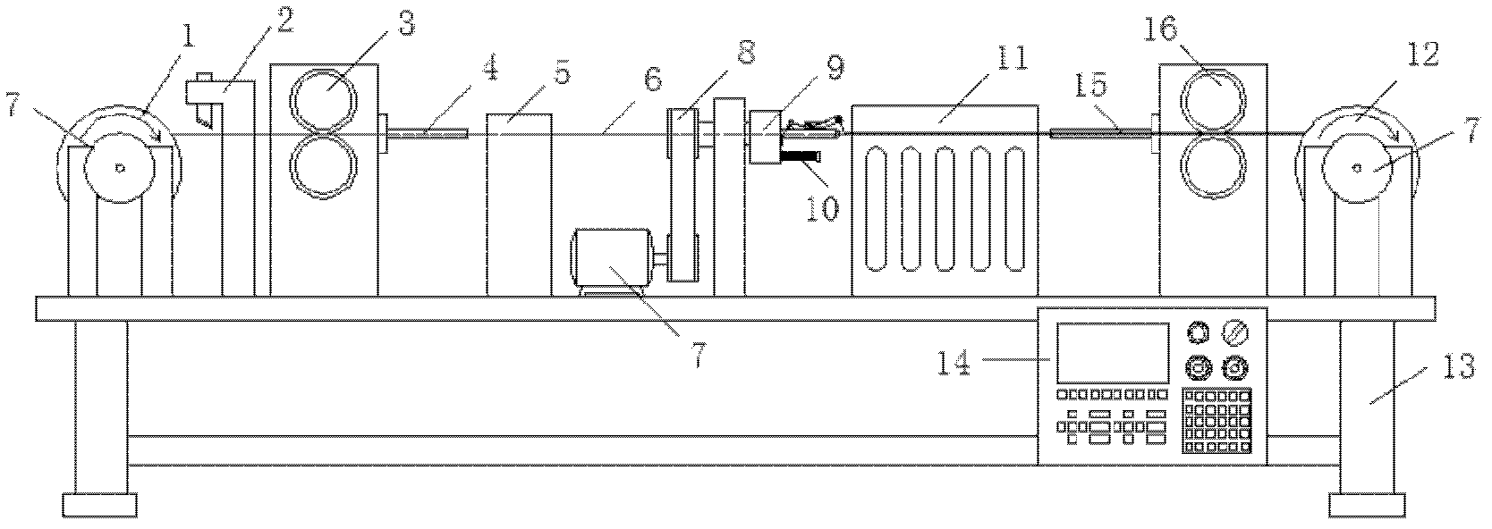
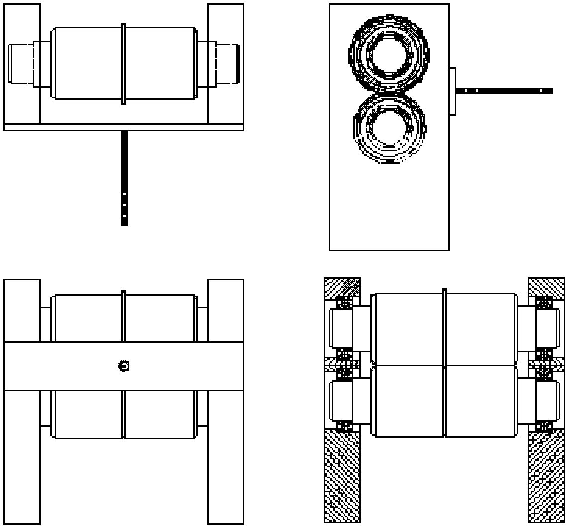
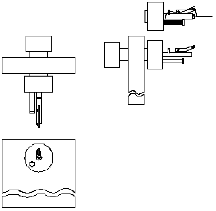

Image

  • New composite wire saw winding equipment
  • New composite wire saw winding equipment
  • New composite wire saw winding equipment

Examples


Embodiment Construction

[0018] refer to Figure 1 to Figure 4 , a new type of compound wire saw winding equipment, including an equipment base 13, a servo motor 7 installed at both ends of the equipment base 13, a pay-off reel 1 and a take-up reel 12 connected to the servo motor 7, and a breaker Thread cutter 2, first tensioning reel head 3, second tensioning reel head 16, first conduit 4, second conduit 15, detachable dipping tank 5, winding arm driven by timing pulley 8 9 and a controller 14, the synchronous pulley 8 is connected with a servo motor 7; the control end of the servo motor 7 is connected with the controller 14; The first tensioner head 3, the dipping tank 5 coated with glue on the surface, enters the winding arm 9 to rotate and wind; the wound wire saw passes through the second tensioner head 16 and winds to On the take-up reel 12; the outlet end of the first tensioner head 3 is provided with the first wire conduit 4, and the inlet end of the second tensioner head 16 is provided with ...


PUM


Abstract

The invention discloses new wire saw winding equipment, comprising an equipment base, a servo motor set at two ends of the equipment base, a pay-off wheel and a take-up wheel in transmission connection with the servo motor and further comprising a wire cutter, a first tension reel head, a second tension reel head, a first conduit, a second conduit, a rubber dipping slot and a winding arm and a controller driven by a synchronous pulley connected with the first servo motor. The control ends of the servo motor are connected with the controller. The inner wire of the pay-off wheel enters into the winding arm to be rotated and wound after in turn passing through the first tension reel head which is used for controlling tension and the rubber dipping slot used for coating the glue on the surface and the wire saw formed by winding is wound on the take-up wheel through the second tension reel head. The composite winding of any length to the wire saw can be carried out and the winding interval of the outer wire can be adjusted. The winding process is controllable and the diameter application scope of the main body of the inner wire and the winding outer wire is wide.

Description

technical field [0001] The invention belongs to the field of wire saw manufacturing for cutting, and in particular relates to a novel composite wire saw winding device. Background technique [0002] The wire cutting process is: the wire saw (steel wire) comes out from the pay-off wheel, and then winds on the winding arm in multiple layers to form a row of wire nets for processing workpieces, and at the same time provides appropriate tension to the wire saw through the tension wheel, Finally back to the reel. When cutting, the workpiece is fed downwards, and the spraying device sprays the slurry on the wire saw, and the wire saw moves in a certain direction, bringing the slurry containing abrasive grains into the cutting area, thereby cutting the workpiece material, realizing Material removal processing. Due to the smooth surface of the wire saw (steel wire), it is difficult for the abrasive particles in the slurry to enter the cutting area with the wire saw, thereby reduci...

Claims


Application Information

Patent Timeline
IPC IPC(8): B21F3/00B21F23/00B23D65/00
Inventor 姚春燕陈思源彭伟
Owner ZHEJIANG UNIV OF TECH
Learn More