Drive device and method for limiting rotational speed
What is Al technical title?
Al technical title is built by PatSnap Al team. It summarizes the technical point description of the patent document.
A technology for driving equipment and equipment, which is applied in the direction of mechanical equipment, transmission device control, transmission devices, etc., can solve the problems of planet carrier speed increase, increase the cost space of driving equipment, etc., and achieve the effect of small temperature increase
Active Publication Date: 2021-09-28
VOITH PATENT GMBH
View PDF9 Cites 0 Cited by
Summary
Abstract
Description
Claims
Application Information
AI Technical Summary
This helps you quickly interpret patents by identifying the three key elements:
Problems solved by technology
Method used
Benefits of technology
Problems solved by technology
This cannot be prevented by a clutch on the auxiliary drive, although this would even allow the auxiliary drive to be protected by disengaging, but then the speed of the planet carrier still rises rapidly
It is proposed in the prior art to prevent this by means of a brake on the planet carrier, however, additional components for the coupling are still required
This increases the cost of the drive equipment and requires more space, two serious disadvantages
Method used
Image
Click on the blue label to locate the original text in one second.
Reading with bidirectional positioning of images and text.
Examples
Embodiment Construction
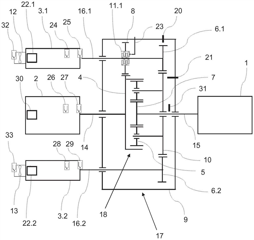
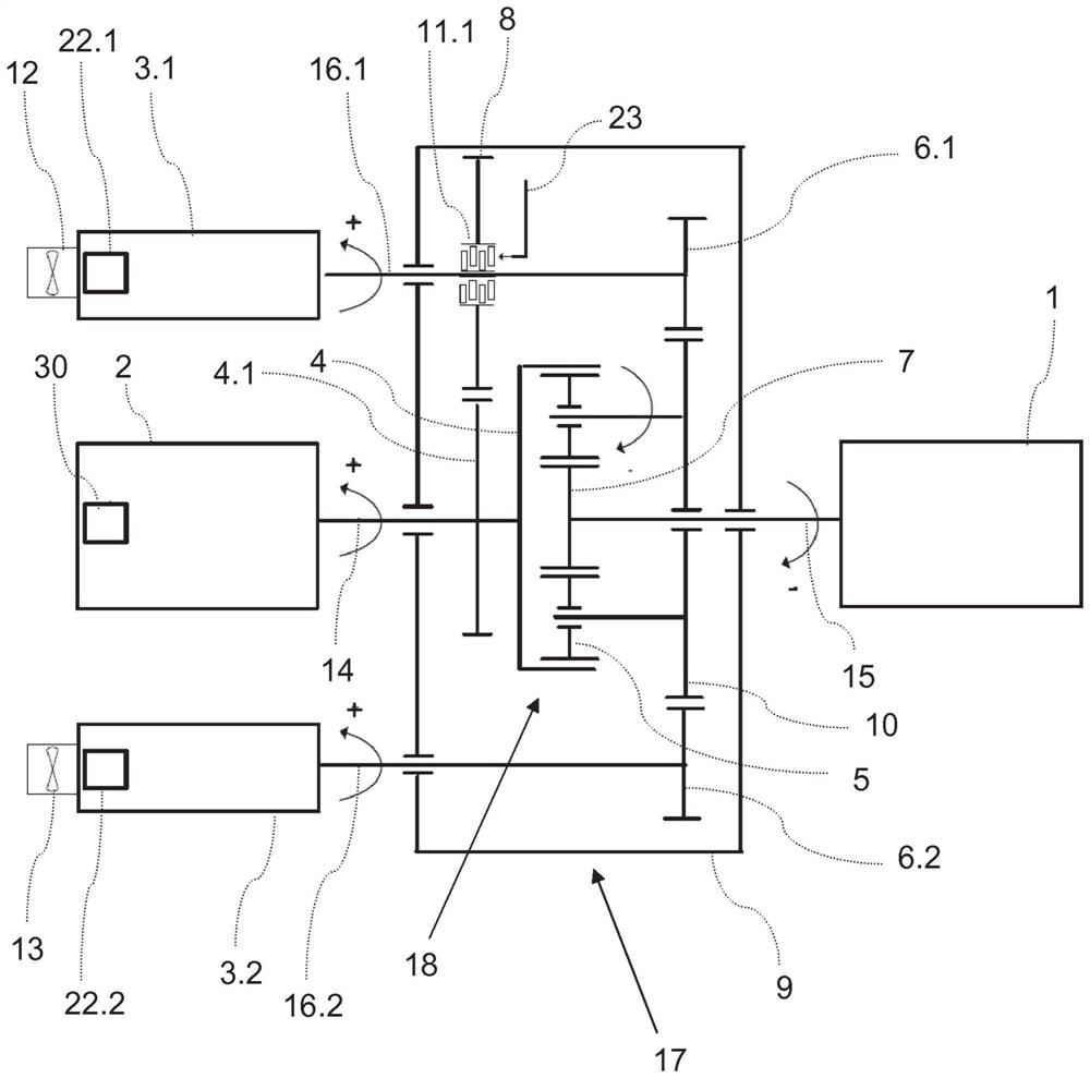
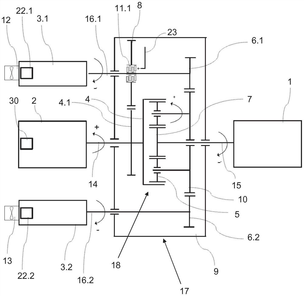
[0062] figure 1 shows a drive device according to the invention, which is coupled to the working machine 1 via an output shaft 15 . And on such a device, the method for limiting the rotational speed according to the invention can be advantageously used. The superposition gear 17 has a housing 9 and includes a planetary gear 18 with a gear ratio i_PG. The input shaft 14 connects the main drive machine 2 with the ring gear 4 of the planetary gear, and the output shaft 15 connects the sun gear 7 with the working machine 1 . The third shaft of the superposition transmission is formed by the auxiliary drive shafts 16.1 and 16.2. These auxiliary drive shafts connect the auxiliary drives 3 . 1 and 3 . 2 to the planetary carrier 10 via the first transmission stages 6 . 1 , 6 . 2 . The planetary carrier 10 carries the planetary gears 5 via planet pins on the one hand, and on the other side the planetary carrier is designed as a gear which forms the first transmission stage 6 with co...
PUM
Abstract
A drive device, comprising: a superimposed transmission (17); a main drive (2) connected to an input shaft (14) of the superimposed transmission; one or more auxiliary drives (3.1, 3.2); and the output shaft (15) of the superimposed transmission device, which can be connected with the working machine (1), wherein the superimposed transmission device (17) comprises a ring gear (4), a sun gear (7), a planet carrier (10) A planetary transmission (18) with a plurality of planetary gears (5), and wherein the input shaft (14) is connected with the ring gear (4), the output shaft (15) is connected with the sun gear (7), and one or more The auxiliary drives (3.1, 3.2) are connected to the planet carrier (10) via a first gear stage (6.1, 6.1a, 6.1b, 6.2, 6.2a, 6.2b) with a constant transmission ratio (i_SG1), wherein in the auxiliary There is an additional drive connection with constant transmission ratios (i_SG1, i_SG2, i_SG3) between the drive (3.1, 3.2) and the ring gear (4) or pinion (4.1) on the input shaft, and wherein in said additional drive A switchable clutch (11.1, 11.2) is present in the connection, which can activate or interrupt the additional transmission connection by means of the first transmission stage (6.1, 6.1a, in the event of interruption by means of the clutch (11.1, 11.2) , 6.1b, 6.2, 6.2a, 6.2b) keep the connection between the auxiliary drive (3.1, 3.2) and the planet carrier (10) active.
Description
technical field [0001] The invention relates to a driving device, which comprises: a superposition transmission device a main drive machine connected to the input shaft of the superposition transmission; one or more auxiliary drives; and an output shaft which may be connected to the working machine, wherein the superposition transmission comprises a ring gear, a sun gear, A planetary transmission of a planet carrier and a plurality of planet gears, and wherein the input shaft is connected to the ring gear, the output shaft is connected to the sun gear, and one or more auxiliary drives are connected to the planet carrier via a transmission stage. [0002] Furthermore, the invention relates to a method for limiting the rotational speed of a main or auxiliary drive in the event of a failure or rapid shutdown of such a drive. Background technique [0003] In a superposition transmission, the two shafts of the planetary transmission are usually driven by mutually independent dr...
Claims
Application Information
Patent Timeline
Application Date:The date an application was filed.
Publication Date:The date a patent or application was officially published.
First Publication Date:The earliest publication date of a patent with the same application number.
Issue Date:Publication date of the patent grant document.
PCT Entry Date:The Entry date of PCT National Phase.
Estimated Expiry Date:The statutory expiry date of a patent right according to the Patent Law, and it is the longest term of protection that the patent right can achieve without the termination of the patent right due to other reasons(Term extension factor has been taken into account ).
Invalid Date:Actual expiry date is based on effective date or publication date of legal transaction data of invalid patent.