Heat exchanger and refrigeration cycle device provided with heat exchanger

A technology of heat exchangers and heat exchange units, applied in heat exchange equipment, compressors with reversible cycles, refrigerators, etc., can solve the problems of heat exchanger temperature efficiency reduction, leakage, etc., and achieve the effect of reducing heat leakage

Active Publication Date: 2019-03-15
MITSUBISHI ELECTRIC CORP
View PDF8 Cites 2 Cited by
  • Summary
  • Abstract
  • Description
  • Claims
  • Application Information

AI Technical Summary

Problems solved by technology

Therefore, there is a problem that the heat of the high temperature part leaks to the low temperature part, and the temperature efficiency in the heat exchanger decreases.

Method used


Image

  • Heat exchanger and refrigeration cycle device provided with heat exchanger
  • Heat exchanger and refrigeration cycle device provided with heat exchanger
  • Heat exchanger and refrigeration cycle device provided with heat exchanger

Examples


Embodiment approach 1

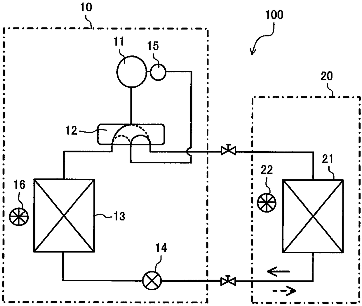
[0019] figure 1 It is a block diagram of an air conditioner equipped with the heat exchanger of Embodiment 1 of this invention. In addition, in figure 1 Here, the solid arrow indicates the flow direction of the refrigerant during the heating operation, and the broken line arrow indicates the flow direction of the refrigerant during the cooling operation.

[0020] Such as figure 1 As shown, the air conditioner 100 including the heat exchanger according to Embodiment 1 includes an outdoor unit 10 and an indoor unit 20.

[0021] The outdoor unit 10 includes a compressor 11 for compressing refrigerant, a four-way valve 12, an outdoor side heat exchanger 13, a pressure reducing device 14, an accumulator 15, and an outdoor side blower 16.

[0022] The compressor 11 sucks in the refrigerant and compresses the refrigerant to a high temperature and high pressure state. The compressor 11 may be a compressor capable of variable operating capacity (frequency), or a compressor of constant capaci...

Embodiment approach 2

[0059] In the first embodiment described above, the number of rows of the heat exchange units 3 is the same in the upstream side heat exchanger 30 and the downstream side heat exchanger 31. However, in the second embodiment, the number of rows of the heat exchange units 3 is the downstream side heat exchanger 31. The configuration in which the number of rows of 3 is smaller than that of the upstream side heat exchanger 30 can reduce the number of heat transfer tubes 2 through which the liquid refrigerant passes. Hereinafter, the description will be focused on the configuration different from Embodiment 2 and Embodiment 1. The structure not described in the second embodiment is the same as the first embodiment.

[0060] Figure 4 It is a schematic perspective view of the outdoor side heat exchanger 13A of Embodiment 2 of this invention.

[0061] The outdoor side heat exchanger 13A of the second embodiment and figure 2 Compared with the outdoor heat exchanger 13 of the first embodi...

Embodiment approach 3

[0076] In the above-mentioned first and second embodiments, the fin pitch, which is the width between the fins, is made the same in the upstream side heat exchanger and the downstream side heat exchanger, but in the third embodiment, the The fin pitch is smaller than that of the upstream heat exchanger. Hereinafter, the description will focus on the differences between the third embodiment and the second embodiment. The structure not described in the third embodiment is the same as that of the second embodiment.

[0077] Image 6 It is a dimensional explanatory diagram of the outdoor heat exchanger 13B in Embodiment 3 of the present invention. in Image 6 In the figure, the interval between adjacent heat sinks 1 is enlarged for convenience of explanation.

[0078] In the outdoor heat exchanger 13B of Embodiment 3, the fin pitch of the fin 1 of the upstream heat exchange unit 3a is set to E, and the fin pitch of the fin 1 of the downstream heat exchange unit 32b is set to F Below...


PUM


Abstract

The purpose of the invention is to provide a heat exchanger and a refrigeration cycle device provided with the heat exchanger that can reduce heat leaks inside a condenser when the heat exchanger functions as a condenser. Provided is a heat exchanger (13) having a plurality of refrigerant channels, wherein each of the plurality of refrigerant channels is a channel from which a refrigerant that flowed in as a gas flows out as a liquid, and each has an upstream-side channel (41-46) through which a gas refrigerant and a gas-liquid two-phase refrigerant pass and a downstream-side channel (47-49) through which a gas-liquid two-phase refrigerant and a liquid refrigerant pass. In addition, the heat exchanger comprises an upstream-side heat exchanger (30) having the upstream-side channel, a downstream-side heat exchanger (31) having the downstream-side channel, and one or more merging devices (51-53) that merge refrigerant flowing out of each upstream-side channel and causes same to flow intothe downstream-side channel, wherein the upstream-side heat exchanger and the downstream-side heat exchanger are configured to be separate from each other, and the number of downstream-side channels is less than the number of upstream-side channels.

Description

Technical field [0001] The present invention relates to a heat exchanger functioning as a condenser and a refrigeration cycle device including the heat exchanger. Background technique [0002] A refrigerant pipe for a conventional refrigeration cycle device connects a compressor, a condenser, a pressure reducing device, and an evaporator in this order to form a refrigeration cycle. Furthermore, as a condenser used in a refrigeration cycle apparatus, there is a condenser having a plurality of refrigerant flow paths connected in parallel (for example, refer to Patent Document 1). Patent Document 1 discloses a technique of setting the height position of the refrigerant outlet of each of the plurality of refrigerant flow paths in order to suppress the uneven flow of the plurality of refrigerant flow paths. [0003] Patent Document 1: Japanese Patent Application Publication No. 2009-287837 [0004] When the heat exchanger functions as a condenser, the refrigerant passing through the plu...

Claims


Application Information

Patent Timeline
Patent Type & Authority Applications(China)
IPC IPC(8): F25B6/04F24F1/18F25B13/00F25B39/04
CPCF24F1/16F24F13/30F28D1/0408F28D1/0417F28D1/0435F28D1/0452F28F9/0275F25B6/04F25B13/00F25B39/04F28D2021/007F28F1/12F28F2215/04
Inventor 山本和英
Owner MITSUBISHI ELECTRIC CORP
Why Eureka
Try Eureka