Focus ring and substrate processing apparatus

a technology of substrate and processing apparatus, which is applied in the direction of coating, chemical vapor deposition coating, plasma technique, etc., can solve the problems of significant and achieve the effect of reducing the leakage of heat transfer gas

Inactive Publication Date: 2018-06-28
TOKYO ELECTRON LTD
View PDF2 Cites 14 Cited by
  • Summary
  • Abstract
  • Description
  • Claims
  • Application Information

AI Technical Summary

Benefits of technology

[0010]It is an object of one aspect of the present invention to reduce the leakage of a heat transfer gas.

Problems solved by technology

This poses a problem in that the leakage of a heat transfer gas becomes significant.

Method used


Image

  • Focus ring and substrate processing apparatus
  • Focus ring and substrate processing apparatus
  • Focus ring and substrate processing apparatus

Examples


Embodiment Construction

[0028]In the following, embodiments of the present invention will be described with reference to the accompanying drawings. In the specification and drawings, elements having substantially the same configurations are referred to by the same numerals and a duplicate description thereof will be omitted.

[General Arrangement of Substrate Processing Apparatus]

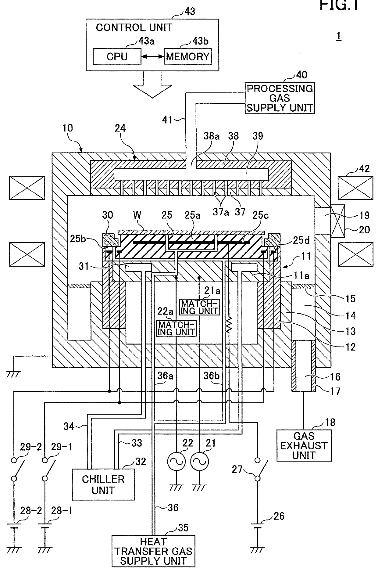
[0029]FIG. 1 is a cross-sectional view illustrating a schematic configuration of a substrate processing apparatus 1 according to an embodiment. In the present embodiment, an example in which the substrate processing apparatus 1 disclosed herein is a reactive ion etching (RIE) substrate processing apparatus will be described. However, the substrate processing apparatus 1 may be applied to apparatuses such as a plasma etching apparatus and a plasma-enhanced chemical vapor deposition (PECVD) apparatus that use surface wave plasma.

[0030]The substrate processing apparatus 1 includes a cylindrical processing chamber 10 made of metal, for ...


PUM

PropertyMeasurementUnit
Young's modulusaaaaaaaaaa
thicknessaaaaaaaaaa
frequencyaaaaaaaaaa

Abstract

A focus ring that surrounds a periphery of a substrate placed on a stage in a processing chamber of a substrate processing apparatus includes a lower surface to contact a peripheral portion of the stage, the lower surface being inclined such that an outer peripheral side becomes lower than an inner peripheral side in a radial direction.

Description

CROSS-REFERENCE TO RELATED APPLICATION[0001]The present application is based upon and claims priority to Japanese Patent Application No. 2016-254318, filed on Dec. 27, 2016, and the Japanese Patent Application No. 2017-224715, filed on Nov. 22, 2017, the entire contents of which are incorporated herein by reference.BACKGROUND OF THE INVENTION1. Field of the Invention[0002]The disclosures herein generally relate to a focus ring and a substrate processing apparatus.2. Description of the Related Art[0003]In a processing chamber of a substrate processing apparatus, a focus ring is disposed to surround a periphery of a substrate placed on an electrostatic chuck. When plasma processing is performed in the processing chamber, the focus ring converges plasma onto the surface of a wafer W so as to improve the efficiency of the plasma processing.[0004]Generally, the focus ring is formed of Si (silicon) and the lower surface is controlled in a horizontal state with no inclination. In recent ye...

Claims


Application Information

Patent Timeline
Patent Type & Authority Applications(United States)
IPC IPC(8): H01L21/3065H01L21/67H01L21/683H05H1/46C23C16/458
CPCH01L21/3065H01L21/67109H01L21/6833H05H1/46C23C16/458H01L21/6831H01L21/68735H01J37/32642H01J37/32724H01J37/32715C23C16/4585C23C16/46C23C16/505
Inventor TSUKAHARA, TOSHIYAISHIBASHI, JUNJITOMIOKA, TAKETOSHISASAKI, YASUHARUUCHIDA, YOHEI
Owner TOKYO ELECTRON LTD
Why Eureka
Try Eureka