
Plate type loop heat pipe evaporator

A loop heat pipe and evaporator technology, applied in the field of heat transfer, can solve the problems of small size, poor pressure bearing capacity of flat plate structure, heat leakage, etc., and achieve the effect of untimely wetting

Active Publication Date: 2018-07-13
CHANGCHUN INST OF OPTICS FINE MECHANICS & PHYSICS CHINESE ACAD OF SCI
View PDF7 Cites 15 Cited by
  • Summary
  • Abstract
  • Description
  • Claims
  • Application Information

AI Technical Summary

Problems solved by technology

The disadvantage is that when the cylindrical evaporator is used in conjunction with the load end surface, an additional saddle is required, which brings additional thermal resistance and temperature difference
[0005] The flat-plate evaporator can be attached to the heating wall, and the temperature is uniform. It is suitable for heat dissipation with limited space and high heat flux. However, due to its compact structure, the heat leakage from the heating surface to the liquid storage chamber through the side wall is serious.
Moreover, the internal pressure capacity of the flat plate structure is not good, and it is prone to deformation
As a result, the size of the existing flat-plate evaporators is generally small, and it is difficult to meet the heat dissipation requirements of large-sized planes

Method used


Image

  • Plate type loop heat pipe evaporator
  • Plate type loop heat pipe evaporator

Examples


Embodiment Construction

[0039] In order to make the object, technical solution and advantages of the present invention clearer, the present invention will be further described in detail below in conjunction with the accompanying drawings and specific embodiments. It should be understood that the specific embodiments described here are only used to explain the present invention, but not to limit the present invention.

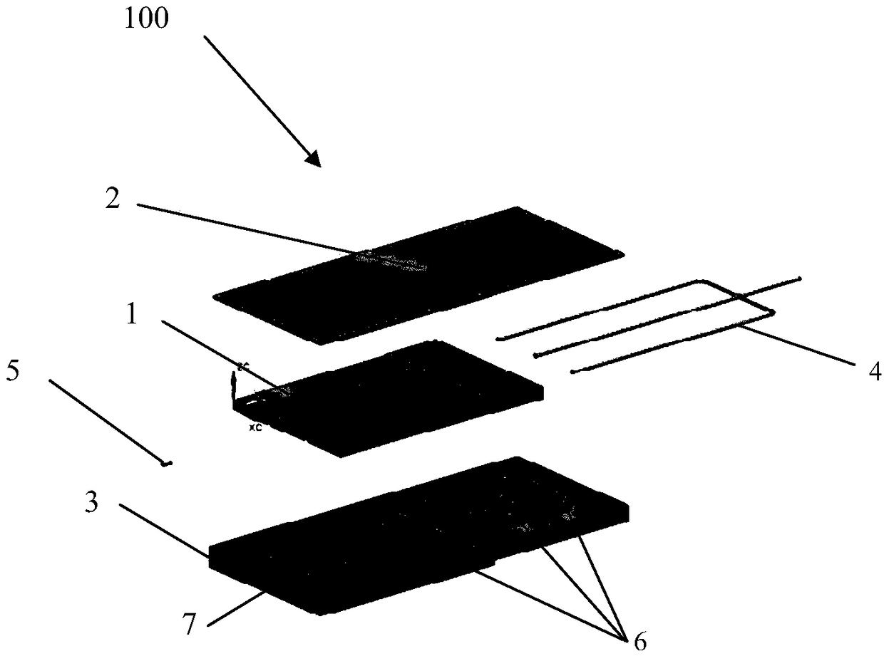
[0040] The invention provides a plate-type loop heat pipe evaporator, which comprises: an evaporator shell, a capillary core, a liquid guide pipe and a steam pipe.

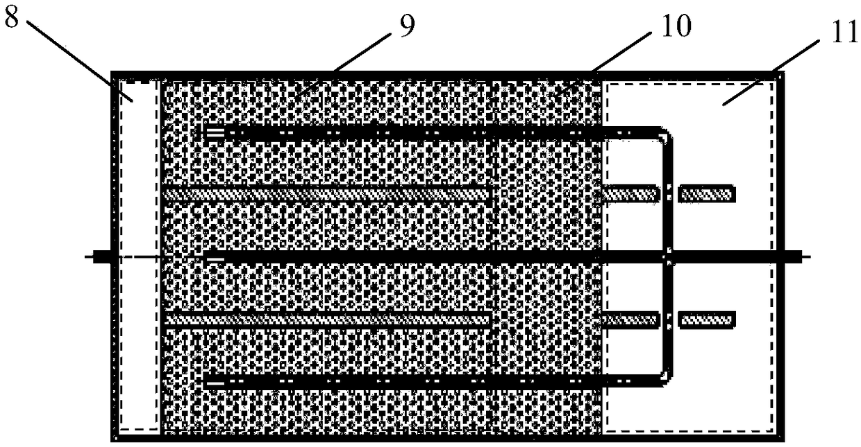
[0041] The shell of the evaporator constructs an inner cavity, which includes a gas collection cavity, an evaporation zone, a buffer zone and a liquid storage cavity.

[0042] The evaporator shell has a plate structure, and the gas collection chamber, evaporation area, buffer zone and liquid storage chamber are arranged along the length direction of the plate structure. In a specific embodiment, the evaporator shell is a ...


PUM


Abstract

The invention relates to a plate type loop heat pipe evaporator. The plate type loop heat pipe evaporator comprises an evaporator shell, a capillary core, a liquid guide pipe and a steam pipe. The evaporator is provided with a plate type structure, and an internal cavity is formed in the evaporator shell. The internal cavity comprises an air collecting cavity, an evaporation area, a buffering areaand a liquid storage cavity. The capillary core is arranged in the internal cavity and occupies the evaporation area and the buffering area. The air colleting cavity and the liquid storage cavity areseparated through the capillary core. The liquid guide pipe is used for guiding incoming flow liquid into the capillary core. Steam in the air collecting cavity flows out through the steam pipe. According to the plate type loop heat pipe evaporator, a slab structure is adopted, and the defects that a cylindrical evaporator is poorly attached to a wall face, and a saddle causes additional temperature differences and heat resistance are overcome.

Description

technical field [0001] The invention belongs to the technical field of heat transfer, in particular, the invention relates to a plate-type loop heat pipe evaporator. Background technique [0002] The loop heat pipe is a high-efficiency heat transfer device based on phase change heat, which can transfer a large amount of heat under the condition of small temperature difference and long distance. It is widely used in thermal control systems in electronic devices, aerospace and other fields. [0003] The main structure of the loop heat pipe includes an evaporator, a liquid storage chamber, a gas-liquid pipeline and a condenser. The interior of the evaporator includes capillary cores, steam channels and other structures. The heat exchange is mainly carried out through two processes of evaporation and condensation of the working fluid, and at the same time, the continuous transportation of the liquid is realized by the capillary action of the porous material on the liquid worki...

Claims


Application Information

Patent Timeline
IPC IPC(8): F28D15/04
CPCF28D15/0266F28D15/043F28D15/046
Inventor 贾卓杭郭亮谭向全黄勇
Owner CHANGCHUN INST OF OPTICS FINE MECHANICS & PHYSICS CHINESE ACAD OF SCI
Learn More