Automatic clamping system and detection method thereof

A detection method and automatic technology, applied in the configuration of indicating equipment/measuring equipment, manufacturing tools, metal processing equipment, etc., can solve problems such as difficult molding, affecting the dimensional accuracy of castings, and difficult air discharge

Inactive Publication Date: 2021-04-20
绍兴闰安电气有限公司
View PDF11 Cites 0 Cited by
  • Summary
  • Abstract
  • Description
  • Claims
  • Application Information

AI Technical Summary

Problems solved by technology

[0004] In view of the above-mentioned related technologies, the inventor believes that there are defects: different molds have different shapes, and there is a certain thickness difference on the molds, and the heat carried in local areas is also different. The application is spraying the entire mold When spraying coolant, there will still be a temperature difference in some areas, and the temperature in some areas may have been lower than the appropriate temperature, while a part with a large thickness and sharp corners has not been cooled, the mold temperature is too low, and the internal structure of the casting Loose, difficult air discharge, difficult to form; mold temperature is too high, the internal structure of the casting is dense, but the casting is easily welded to the cavity, and the sticky mold is not easy to unload the casting. At the same time, too high temperature will cause the mold itself to expand and affect the casting Dimensional accuracy

Method used


Image

  • Automatic clamping system and detection method thereof
  • Automatic clamping system and detection method thereof
  • Automatic clamping system and detection method thereof

Examples


Embodiment Construction

[0048] The following is attached Figure 1-6 The application is described in further detail.

[0049] The embodiment of the present application discloses an automatic clamping system.

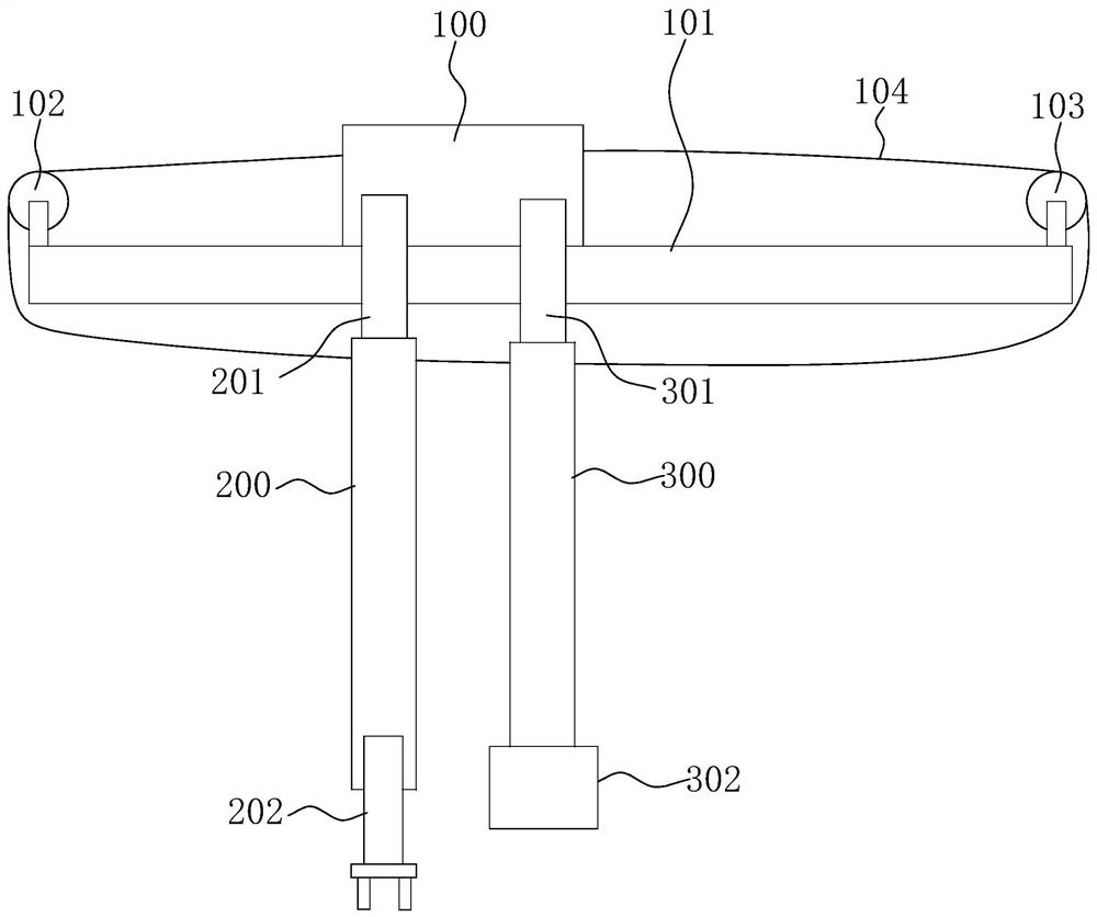
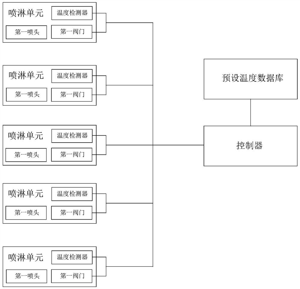
[0050] An automatic gripping system such as figure 2 As shown, including main rack, controller and preset temperature database. Applied to die casting machine.

[0051] Such as figure 1 As shown, a drive assembly is provided below the main frame 100, and the drive assembly includes a horizontal guide rail 101 arranged below the main frame 100. The guide rail 101 is fixed on the wall so that the main frame 100 can move on the guide rail 101. One end is provided with a first gear 102, and the other end of the guide rail 101 is provided with a second gear 103, and a chain 104 is connected between the first gear 102 and the second gear 103, and one end of the chain 104 is fixed on the main frame 100 near the first gear. One end of the gear 102, the chain 104 meshes through the first gear 102,...


PUM


Abstract

The invention relates to an automatic clamping system. The automatic clamping system comprises a main frame, a driving assembly used for driving the main frame to move is arranged on the main frame, a first arm and a second arm are arranged on the main frame, a first lifting assembly is arranged between the first arm and the main frame, a second lifting assembly is arranged between the second arm and the main frame, a clamping assembly is arranged on the first arm, a spraying assembly is arranged on the second arm, the spraying assembly comprises a plurality of spraying units, and each spraying unit corresponds to one and merely one die-casting die local area. The automatic clamping system and a detection method thereof have the effects that a controller obtains the temperature, detected by each spraying unit, of the corresponding die-casting mold local area and compares the temperature with the preset temperature of the current material, so that spraying of cooling liquid to the die-casting mold local area corresponding to the current spraying unit or stopping of spraying of the cooling liquid is controlled, the temperature of each die-casting die local area will not be too high or too low, and the problem in the related technology that temperature difference exsists among local portions since integral spraying is performed on the die-casting die is solved.

Description

technical field [0001] The present application relates to the field of die-casting machines, in particular to an automatic clamping system and a detection method thereof. Background technique [0002] With the advancement of science and technology and industrial production, die-casting technology has also developed extremely rapidly. Die-casting machines are machines used for die-casting, including hot-press chambers and cold-press chambers, which are later divided into straight and horizontal. There are two types. The die-casting machine hydraulically injects molten metal into the mold for cooling and forming under pressure. After the mold is opened, a solid metal casting can be obtained; as the die-casting process progresses, the mold temperature will gradually rise. If the mold temperature is too high, it will It will affect the quality of the casting and the life of the mold, so it is necessary to cool the die-casting mold after one die-casting is completed to ensure tha...

Claims


Application Information

Patent Timeline
Patent Type & Authority Applications(China)
IPC IPC(8): B22D17/22B22D17/20B22D17/32B22D2/00
Inventor 蔡国华赵明星
Owner 绍兴闰安电气有限公司
Why Eureka
Try Eureka