A Gas Density Monitoring System
A gas density and monitoring system technology, applied in the field of electric power, can solve problems such as hidden dangers in safe operation and affecting electrical performance of equipment, and achieve the effects of improving test accuracy, ensuring grid safety, and measuring accuracy
- Summary
- Abstract
- Description
- Claims
- Application Information
AI Technical Summary
Problems solved by technology
Method used
Image
Examples
Embodiment 1
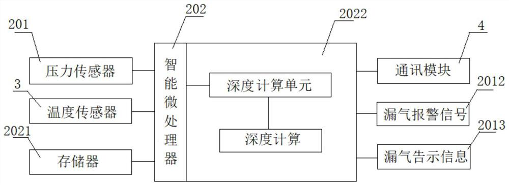
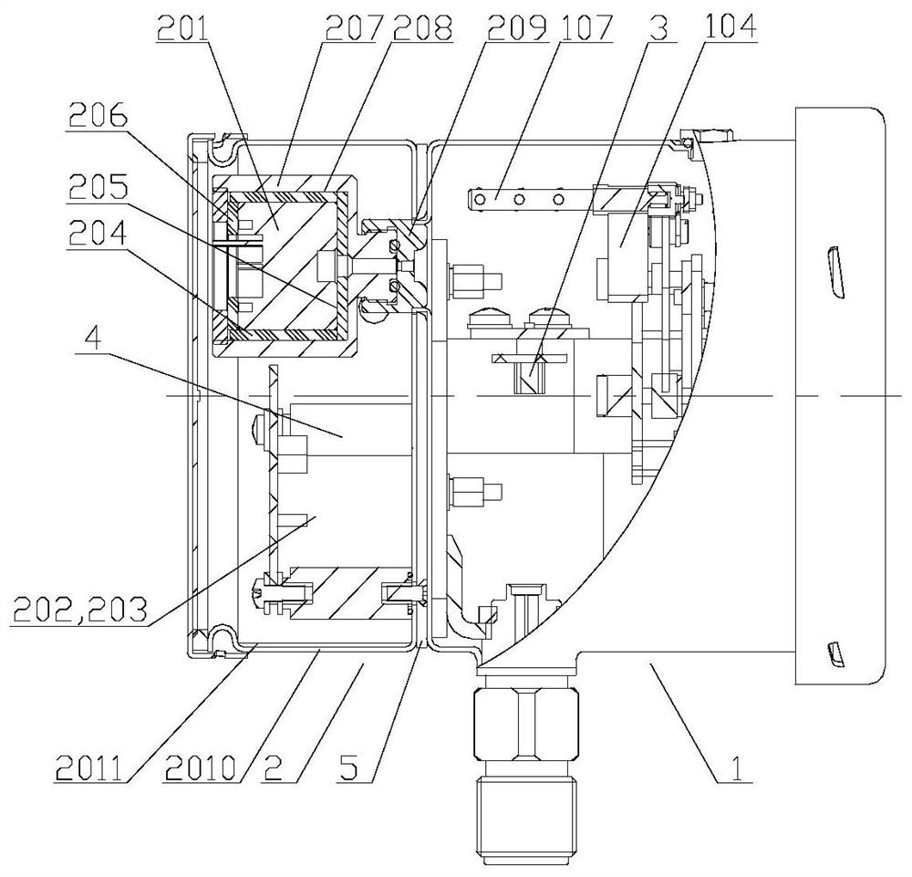
[0078] figure 1 It is a schematic circuit diagram of a gas density monitor used for high-voltage electrical equipment in Embodiment 1 of the present invention. Such as figure 1 As shown, a gas density monitor includes: an intelligent microprocessor 202 , a pressure sensor 201 , a temperature sensor 3 , a communication module 4 , and a memory 2021 . The pressure sensor 201 communicates with the gas path of the gas density monitor. The intelligent microprocessor 202 is connected with the temperature sensor 3 , the pressure sensor 201 and the communication module 4 respectively.
[0079] The intelligent microprocessor 202 obtains the pressure signal collected by the pressure sensor 201 and the temperature signal collected by the temperature sensor 3 at a set sampling frequency, and calculates the corresponding gas density value P according to the gas pressure-temperature characteristic 20 (that is, the pressure value P at 20°C 20 ). Described intelligent microprocessor 202 c...
Embodiment 2
[0105] Figure 4 It is a gas density monitoring system of the second embodiment of the present invention. Such as Figure 4 As shown, multiple high-voltage electrical equipment equipped with sulfur hexafluoride gas chambers and multiple gas density monitors are sequentially connected to the background monitoring terminal through a hub and an IEC61850 protocol converter. Wherein, each gas density monitor is respectively arranged on the high-voltage electrical equipment of the corresponding sulfur hexafluoride gas chamber.
[0106] In this embodiment, the background monitoring terminal PC communicates with multiple hubs HUB (HUB1, HUB2, ... HUBm) through the hub HUB0. Each hub HUB is connected to a group of gas density monitors, for example, hub HUB1 is connected to gas density monitors Z11, Z12, ... Z1n, hub HUB2 is connected to gas density monitors Z21, Z22, ... Z2n, ..., and hub HUBm is connected to gas Density monitors Zm1, Zm2, ... Zmn, where m and n are both natural num...
Embodiment 3
[0109] Figure 5 It is a gas density monitoring system according to the third embodiment of the present invention. Compared with the second embodiment, this embodiment adds a network switch Gateway, a comprehensive application server Server, and a protocol converter / online monitoring intelligent unit ProC. In this embodiment, the background monitoring terminal PC is connected to two comprehensive application servers Server1 and Server2 through the network switch Gateway, and the two comprehensive application servers Server1 and Server2 communicate with multiple protocol converters / online monitoring intelligence through the station control layer A network and B network. The unit ProC (ProC1, ProC2, ... ProCn) communicates, and the protocol converter / online monitoring intelligent unit ProC communicates with multiple hubs HUB (HUB1, HUB2, ... HUBm) through the R5485 network. Each hub HUB is connected to a group of gas density monitors, for example, hub HUB1 is connected to gas d...
PUM
 Abstract
Description
Claims
Application Information
 - R&D
- Intellectual Property
- Life Sciences
- Materials
- Tech Scout
- Unparalleled Data Quality
- Higher Quality Content
- 60% Fewer Hallucinations
Browse by: Latest US Patents, China's latest patents, Technical Efficacy Thesaurus, Application Domain, Technology Topic, Popular Technical Reports.
© 2025 PatSnap. All rights reserved.Legal|Privacy policy|Modern Slavery Act Transparency Statement|Sitemap|About US| Contact US: help@patsnap.com


