
Photolithography method

A technology of lithography equipment and surface film, which is applied in the field of lithography and can solve the problems of side effects and impact of surface film

Active Publication Date: 2020-12-25
ASML NETHERLANDS BV
View PDF4 Cites 0 Cited by
  • Summary
  • Abstract
  • Description
  • Claims
  • Application Information

AI Technical Summary

Problems solved by technology

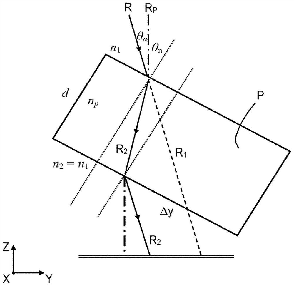
[0006] Although pellicles provide useful and valuable functions, pellicles can cause undesired side effects as they themselves will affect the image projected onto the substrate by the lithographic apparatus

Method used


Image

  • Photolithography method
  • Photolithography method
  • Photolithography method

Examples


Embodiment Construction

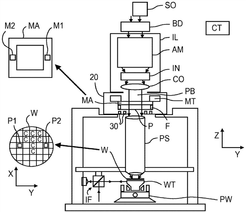
[0054] Although specific reference may be made herein to the use of lithographic apparatus in IC fabrication, it should be understood that the lithographic apparatus described herein may have other applications, such as fabrication of integrated optical systems, Guiding and detecting patterns, liquid crystal displays (LCDs), thin-film magnetic heads, and more. Those skilled in the art will appreciate that any term "wafer" or "die" used herein may be considered synonymous with the more general terms "substrate" or "target portion," respectively, in the context of these alternative applications. The substrates referred to herein may be processed, before or after exposure, in eg a track (a tool that typically applies a layer of resist to a substrate and develops the exposed resist) or a metrology or inspection tool. Where applicable, the disclosure herein may be applied to these and other substrate processing tools. Furthermore, a substrate may be processed more than once, eg, t...


PUM

PropertyMeasurementUnit
thicknessaaaaaaaaaa

Abstract

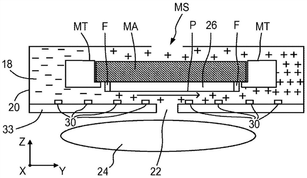
A lithographic apparatus comprising a support structure configured to support a patterning device and an associated pellicle, the patterning device capable of imparting a radiation beam pattern in a cross-section of the radiation beam to form a pattern a patterned radiation beam; and a projection system configured to project the patterned radiation beam onto a target portion of a substrate, wherein the support structure is located in a housing and wherein a pressure sensor is located in the housing body.

Description

[0001] Cross References to Related Applications [0002] This application claims priority from European Application No. 16180548.6 filed on 21.07.2016, the entire content of which is hereby incorporated by reference. technical field [0003] The invention relates to a photolithography method, and also relates to a photolithography equipment. Background technique [0004] A lithographic apparatus is a machine that applies a desired pattern onto a target portion of a substrate. For example, lithographic equipment may be used in the manufacture of integrated circuits (ICs). In this case, a mask (alternatively referred to as a mask or reticle) can be used to create a circuit pattern corresponding to a single layer of the IC, and this pattern can be imaged onto a layer of radiation-sensitive material (resist). On a target portion (eg, a portion including a die, a die or several dies) on a substrate (eg, a silicon wafer). In general, a single substrate will contain a network of...

Claims


Application Information

Patent Timeline
Patent Type & Authority Patents(China)
IPC IPC(8): G03F7/20
CPCG03F7/70308G03F7/70866G03F7/70983G03F7/7085G03F1/62G03F1/64
Inventor A·B·珍宁科L·J·A·凡鲍克霍文S·H·范德穆伦黄仰山F·拉托雷拜尔拉克·摩艾斯特S·C·J·A·凯吉E·范德布林克C·H·斯豪滕H·P·T·托尔斯马
Owner ASML NETHERLANDS BV
Learn More