antenna
A technology of antenna and antenna unit, applied in the direction of antenna coupling, etc., can solve the problem of high side lobe
- Summary
- Abstract
- Description
- Claims
- Application Information
AI Technical Summary
Problems solved by technology
Method used
Image
Examples
example 1
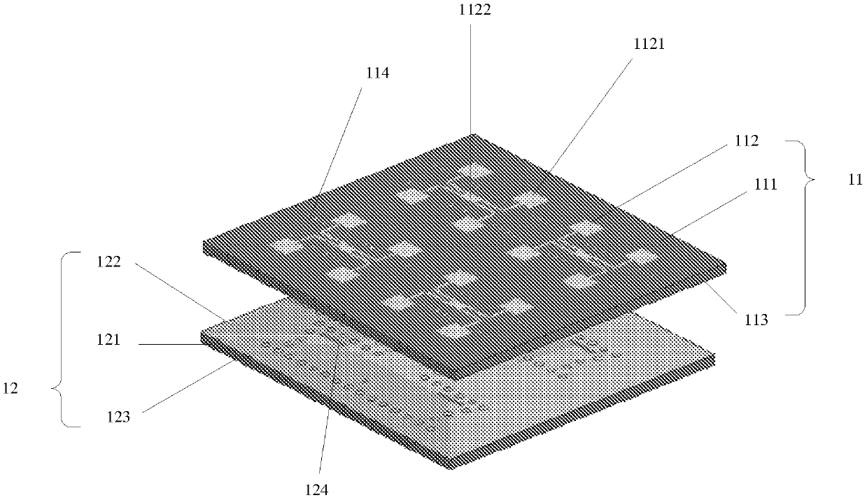
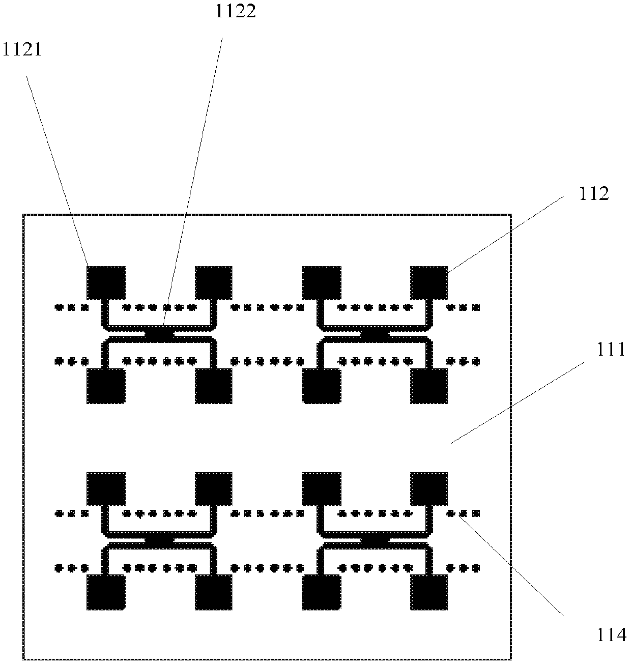
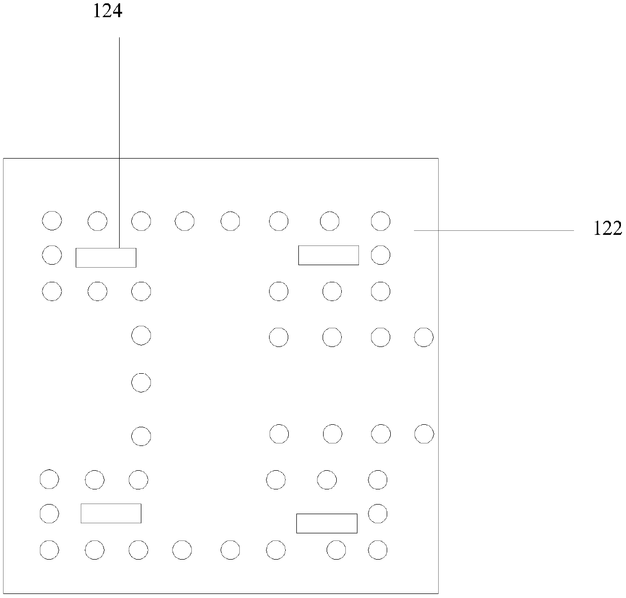
[0040] Example one: Figure 5 A schematic structural diagram of a radiator provided by another embodiment of the present invention, Image 6 A schematic structural view of the power feed body provided for another embodiment of the present invention, such as Figure 5 and Image 6 As shown, the radiator includes: a first substrate 111, a first copper clad layer 112 disposed on the upper surface of the first substrate 111, and a second copper clad layer disposed on the lower surface of the first substrate 111; There are two sets of metal through holes 114 penetrating the upper surface and the lower surface of the first substrate 111 from top to bottom, and the two sets of metal through holes 114 are respectively located on both sides of the corresponding second feed slot 124, The opening of each metal via 1141 in the two groups of metal vias 114 is rectangular.
[0041] which based on Figure 5 The feeding principle of the antenna structure shown is based on figure 1 The fe...
example 2
[0042] Example two: Figure 7 A schematic structural diagram of a radiator provided in yet another embodiment of the present invention, such as Image 6 and Figure 7 As shown, the radiator includes: a first substrate 111, a first copper clad layer 112 disposed on the upper surface of the first substrate 111, and a second copper clad layer disposed on the lower surface of the first substrate 111; There are two sets of metal through holes 114 penetrating the first substrate 111 from top to bottom, and the two sets of metal through holes 114 are respectively located on both sides of the corresponding second feed slot 124, and the two sets of metal through holes 114 One group of metal vias includes a plurality of metal vias 1141, and the opening of each metal via 1141 is rectangular; the other group of metal vias includes a plurality of metal vias 1141, and the opening of each metal via 1141 is The shape is circular, taking each of the second feed slots 124 as a symmetry axis, ...
example 3
[0044] Example three: Figure 8 A schematic structural diagram of a radiator provided for another embodiment of the present invention, such as Image 6 and Figure 8 As shown, the radiator includes: a first substrate 111, a first copper clad layer 112 disposed on the upper surface of the first substrate 111, and a second copper clad layer disposed on the lower surface of the first substrate 111; There are two sets of metal through holes 114 penetrating the first substrate 111 from top to bottom. The two sets of metal through holes 114 are respectively located on both sides of the corresponding second feed slot 124. One of the two sets of metal through holes 114 Each group of metal vias includes a plurality of metal vias 1141, wherein the openings of the metal vias 1141 are all circular, and the apertures of each metal via 1141 are not completely the same, and the openings of each metal via 1141 are circular , taking each of the second feeding slots 124 as the axis of symmetr...
PUM
 Abstract
Description
Claims
Application Information
 - R&D
- Intellectual Property
- Life Sciences
- Materials
- Tech Scout
- Unparalleled Data Quality
- Higher Quality Content
- 60% Fewer Hallucinations
Browse by: Latest US Patents, China's latest patents, Technical Efficacy Thesaurus, Application Domain, Technology Topic, Popular Technical Reports.
© 2025 PatSnap. All rights reserved.Legal|Privacy policy|Modern Slavery Act Transparency Statement|Sitemap|About US| Contact US: help@patsnap.com


