Expandable cryoablation catheter

A technology for ablating catheters and freezing devices, applied in catheters, cooling surgical instruments, medical science, etc., can solve the problems of large application, large expansion and contraction force of freezing units, and breakage, etc., to reduce the influence of shape changes, The effect of improving the freezing speed and prolonging the service life

Pending Publication Date: 2019-03-19
NINGBO SHENGJIEKANG BIOTECH
View PDF0 Cites 7 Cited by
  • Summary
  • Abstract
  • Description
  • Claims
  • Application Information

AI Technical Summary

Problems solved by technology

[0004] However, in the application of the natural cavity of the human body, most of the existing cryoablation instruments perform cryoablation of the entire circumference area. It is a natural channel with cilia swinging and peristaltic functions), and there are defects in the application; for example, as a relatively common application method, the expandable part of the existing cryoablation catheter mostly adopts a balloon structure, and the balloon is formed in the balloon. Ultra-low temperature, through the contact between the balloon wall and the tissue for heat exchange, to achieve the purpose of ablation therapy. With this structure, all the contact area of ​​the balloon will be cryoablated. When used in the natural cavity, the entire cavity circumference (contact part) will be ablation, thereby causing damage to the vital physiological functions of the lumen
Moreover, the existing cryoablation technology also has the disadvantage of being subjected to a large force during expansion and contraction, and requires a large force to be applied during use, which is inconvenient for the operator; for example, as a relatively common application method, the existing The cryoablation catheter adopts a cryounit with an expandable structure, most of which are equipped with a central mandrel and a sheath. Connection, when the freezing unit expands or contracts, the force on the mandrel is very large, which may easily lead to deformation or even breakage of the mandrel, resulting in a relatively large force of expansion and contraction of the freezing unit. At the same time, the shape change of the freezing unit is limited by the mandrel , the shape of the predetermined expansion and contraction is prone to change

Method used


Image

  • Expandable cryoablation catheter
  • Expandable cryoablation catheter
  • Expandable cryoablation catheter

Examples


Embodiment 1

[0059] This embodiment provides an expandable cryoablation catheter.

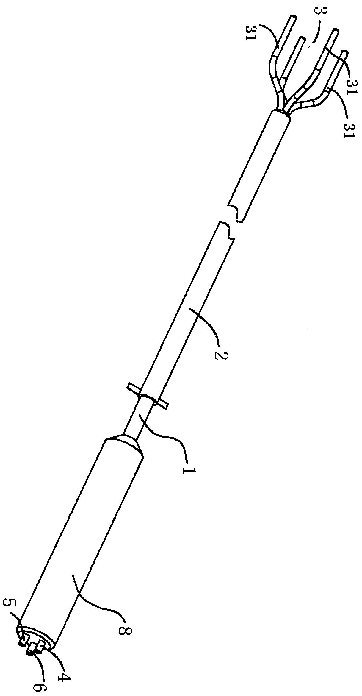
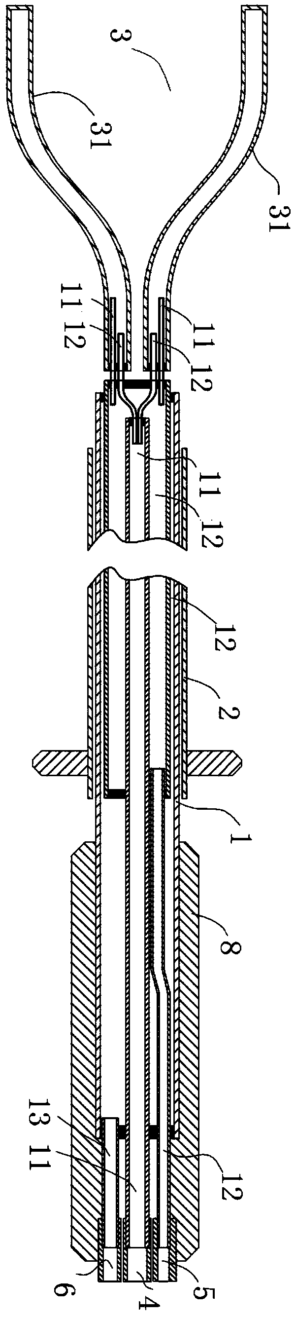
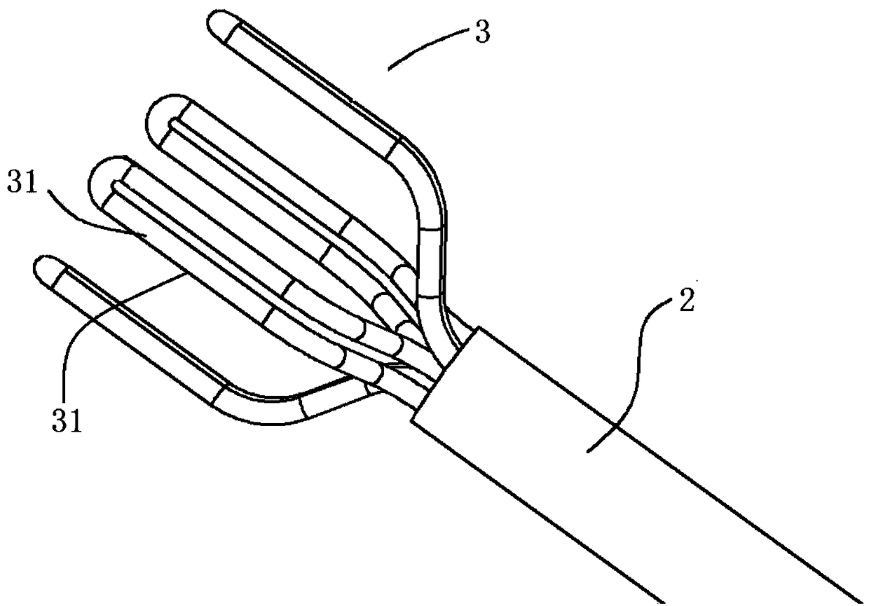
[0060] see figure 1 and figure 2 As shown, an expandable cryoablation catheter described in this embodiment is a tubular structure, including a tubular body 1 with a hollow lumen, a sheath tube 2 and a cryoablation device 3, and the cryoablation device 3 is arranged and communicated with the The far end of the tube body 1, the two ends of the tube body 1 are closed, wherein: the freezing device 3 is composed of a plurality of freezing units 31, the distal ends of the plurality of freezing units 31 are independent from each other, and the freezing units 31 are in the When released from the distal end of the sheath tube 2, it can return to the set shape; the tube body 1 is movably arranged in the lumen of the sheath tube 2, and the distal end of the tube body 1 It is connected and communicated with the proximal ends of several freezing units 31, when the tubular body 1 and the sheath tube 2 are relatively ...

Embodiment 2

[0066] Such as Figure 17-19 As shown, this embodiment shows three specific positional relationship structures of the air inlet pipeline 11 and the air return pipeline 12 of the expandable cryoablation catheter in Embodiment 1, specifically: the air inlet pipeline 11 and the air return pipeline The roads 12 are coaxial or arranged in parallel, and the air intake pipe 11 is arranged inside the return air pipe 12, such as Figure 17 shown; or the return air pipeline 12 is arranged inside the air intake pipeline 11, such as Figure 18 shown; or the air intake pipeline 11 and the return air pipeline 12 are arranged side by side, such as Figure 19shown. The distal ends of the air intake pipeline 11 and the return air pipeline 12 communicate with the proximal ends of the plurality of refrigeration units 31 respectively. To form the circulation of the refrigerant to realize cryoablation.

[0067] As a preferred technical solution, such as figure 2 As shown, at least one air in...

Embodiment 3

[0072] In this embodiment, the cryounit 31 of the expandable cryoablation catheter in Embodiment 1 is bent, and its distal end is closed, and can be deformed under the action of external force and memorize the deformation when the external force disappears. The freezing unit 31 is of two different shapes, one, such as Figure 4-7 As shown, the refrigerating unit 31 is made of a hollow tube with a closed far end, and the near ends of the hollow tube are connected to the air intake pipeline 11 and the return air pipeline 12; image 3 As shown, the freezing unit 31 is composed of two hollow tubes, the distal ends of the two hollow tubes communicate with each other, and the proximal ends of the two hollow tubes communicate with the air intake pipeline 11 and the return air pipeline 12 respectively. . A plurality of freezing units 31 are connected to the distal end of the tube body 1 as independent entities, and can be set in different shapes according to different cavity shapes i...


PUM


Abstract

The invention discloses an expandable cryoablation catheter. The catheter includes a catheter body, a sheath tube and a refrigerating device. The refrigerating device is arranged at and connected withthe distal end of the catheter body. The refrigerating device is composed of several refrigerating units. The distal ends of several refrigerating units are independent of each other, and the refrigerating unit can be restored to a set shape when released from the distal end of the sheath tube. The catheter body is movably arranged in a cavity of the sheath tube, the tail end of the catheter bodyis connected and communicated with the near ends of the refrigerating units, and when the catheter body and the sheath tube displace relatively, the distal ends of the refrigerating units displace synchronously relative to the distal end of the sheath tube to achieve expansion or contraction. The catheter can achieve full freezing in the circumferential direction of the natural cavity and also achieve uniform interval freezing in the circumferential direction of the natural cavity, in order to retain the important physiological function of the original cavity. Meanwhile the expansion and contraction stress of the refrigerating units can be reduced, and the influence of expansion and contraction on the shape change of the refrigerating units is reduced.

Description

technical field [0001] The invention relates to the technical field of cryoablation, in particular to an expandable cryoablation catheter. Background technique [0002] Intervention therapy in the natural cavity of the human body has attracted more and more attention, and there are more and more corresponding treatment devices and methods, and the clinical treatment effect has been widely recognized. At present, radiofrequency ablation is widely used and developed rapidly. Although successful in several areas, radiofrequency ablation has several major disadvantages, including incomplete ablation, often lack of visualization during catheterization, potential overlap during treatment (where some areas receive energy from other areas) twice), tissue charring and need for frequent debridement, frequent need for additional doses of energy after debridement, and potential perforation of body cavities or chambers due to the rigidity of RF electrodes. [0003] In view of the above...

Claims


Application Information

Patent Timeline
Patent Type & Authority Applications(China)
IPC IPC(8): A61B18/02
CPCA61B18/02A61B2018/0212A61B2018/0262
Inventor 俞鹏邢宗江宋超万献波
Owner NINGBO SHENGJIEKANG BIOTECH
Why Eureka
Try Eureka