braided support

A braided wire and bare stent technology, applied in the field of medical devices, can solve the problems of increasing the sheathing size of the braided stent 11 and reducing the flexibility of the distal end of the braided stent 11, so as to reduce the risk of fatigue fracture, achieve consistent axial force, and avoid The effect of the assembly problem

Active Publication Date: 2021-03-30
LIFETECH SCI (SHENZHEN) CO LTD
View PDF8 Cites 0 Cited by
  • Summary
  • Abstract
  • Description
  • Claims
  • Application Information

AI Technical Summary

Problems solved by technology

However, this design will increase the sheath size of the braided stent 11, and may also reduce the flexibility of the distal end of the braided stent 11.

Method used


Image

  • braided support
  • braided support
  • braided support

Examples


Embodiment Construction

[0021] In order to make the above objects, features and advantages of the present invention more comprehensible, specific implementations of the present invention will be described in detail below in conjunction with the accompanying drawings. In the following description, numerous specific details are set forth in order to provide a thorough understanding of the present invention. However, the present invention can be implemented in many other ways different from those described here, and those skilled in the art can make similar improvements without departing from the connotation of the present invention, so the present invention is not limited by the specific implementations disclosed below.

[0022] It should be noted that when an element is referred to as being “fixed on” or “disposed on” another element, it may be directly on the other element or there may be an intervening element. When an element is referred to as being "connected to" another element, it can be directl...


PUM


Abstract

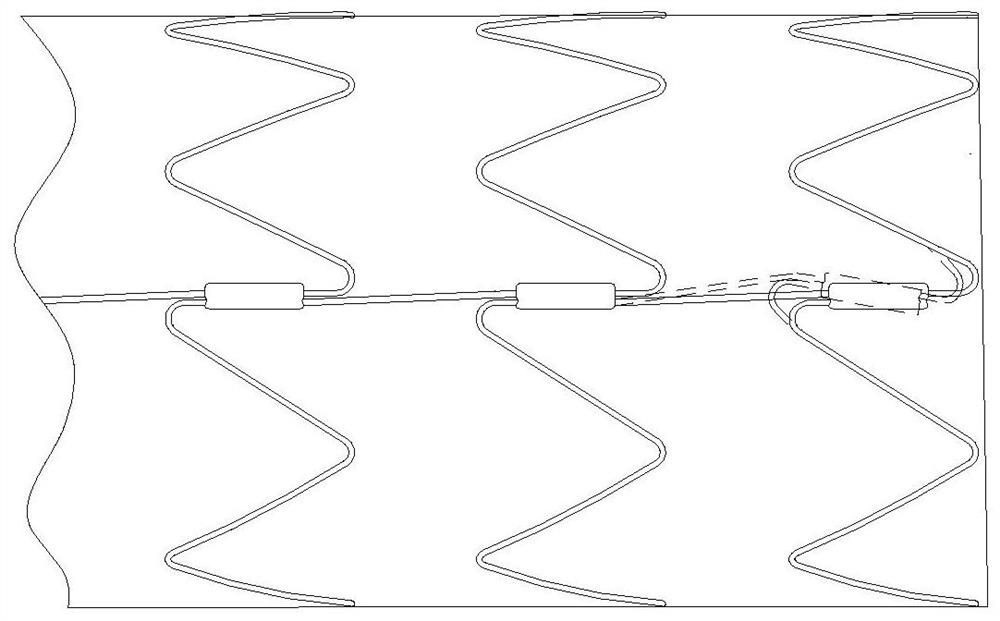
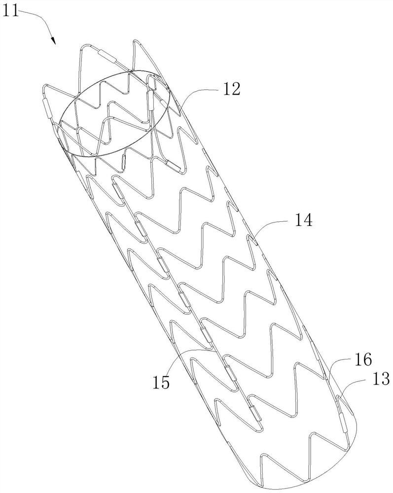
A braided stent (10, 20, 30, 40, and 60), comprising a body section (100). The body section (100) comprises sequentially from the proximal end to the distal end a proximal-end corrugated ring (101, 301, 401, and 601), multiple intermediate corrugated rings (102 and 402), and a distal-end corrugated ring (103, 203, 303, 403, and 603). The body section (100) also comprises a connector (105, 205, 305, 405, and 605) extending in the axial direction of the body section (100). The connector (105, 205, 305, 405, and 605) connects the multiple intermediate corrugated rings (102 and 402). The connector (105, 205, 305, 405, and 605) is extended to intersect the distal-end corrugated ring (103, 203, 303, 403, and 603), and, a braiding wire used for braiding the connector (105, 205, 305, 405, and 605) is continuously braided to form the distal-end corrugated ring (103, 203, 303, 403, and 603) and to allow the point of intersection between the connector (105, 205, 305, 405, and 605) and the distal-end corrugated ring (103) to be located at a crest (1033) or a trough of the distal-end corrugated ring (103, 203, 303, 403, and 603). The braided stent (10, 20, 30, 40, and 60) reduces the risk of fatigue fracturing of the connector (105, 205, 305, 405, and 605) due to an internal torsional stress, also provides an axial force of increased consistency, and also prevents the problem with assembly brought forth by multiple connectors.

Description

technical field [0001] The invention relates to the field of medical instruments, in particular to a braided bracket. Background technique [0002] For stents used in blood vessels, especially for the treatment of aortic aneurysms, the overall stent needs to have better anti-shortage performance, otherwise, the part of the lumen stent that isolates the tumor cavity may slip due to shortening Into the tumor cavity, causing failure, and even endangering the life of the patient. At the same time, the proximal and distal ends of the lumen stent need to be very flexible, otherwise, due to the impact of blood flow and the periodic pulsation of the blood vessel, the proximal and distal ends of the stent will cause continuous stimulation to the vessel wall, causing serious damage to the vessel wall, resulting in proximal or distal breach. Therefore, the existing luminal stents are often designed with longitudinal connectors in the middle of the stent to connect the adjacent wavefo...

Claims


Application Information

Patent Timeline
Patent Type & Authority Patents(China)
IPC IPC(8): A61F2/90A61F2/94
CPCA61F2/90A61F2/94
Inventor 浦文俊肖本好
Owner LIFETECH SCI (SHENZHEN) CO LTD
Why Eureka
Try Eureka