Welding method for cantilever structure with rib plates

A welding method and ribbed plate technology, applied in welding equipment, welding equipment, auxiliary welding equipment, etc., can solve problems that affect the overall quality and performance of the product, difficult to guarantee dimensional accuracy, deformation of structural components, etc., to reduce the risk of fatigue fracture , Reduce welding deformation, reduce the effect of residual stress

Active Publication Date: 2022-07-22
CHINA THREE GORGES PROJECTS DEV CO LTD
View PDF9 Cites 0 Cited by
  • Summary
  • Abstract
  • Description
  • Claims
  • Application Information

AI Technical Summary

Problems solved by technology

In traditional welding, the fillet welds of the rib plate and the vertical plate are generally welded first, and then the butt joints of the flat plate and the vertical plate are welded. This method is likely to cause the flat plate to warp upward during the welding process, the deformation of the structural components is large, and the dimensional accuracy is difficult to guarantee. Affect overall product quality and performance

Method used


Image

  • Welding method for cantilever structure with rib plates
  • Welding method for cantilever structure with rib plates
  • Welding method for cantilever structure with rib plates

Examples


Embodiment 1

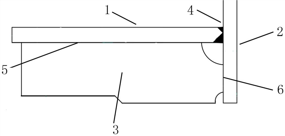
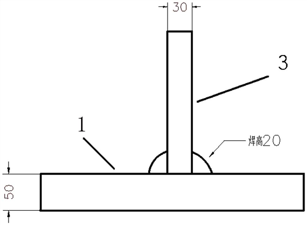
[0041] Provide flat plate 1, vertical plate 2 and vertical rib plate 3 with steel plate material of Q345. The thickness of flat plate 1, vertical plate 2 and vertical rib plate 3 are 50mm, 80mm and 30mm respectively, and the length of flat plate 1 is 1500mm and the width is 800mm. The K-shaped grooves of the flat plate 1 and the vertical plate 2 are designed to be 17mm in depth at the upper part and 33mm in the lower part. The vertical rib plate 3 is welded with the flat plate 1 and the vertical plate 2 by fillet welding, and the welding height is 20mm.

[0042] The flat plate 1 and the vertical rib plate 3 are connected by fillet welding. Since the flat plate 1 and the vertical rib plate 3 can be flipped freely, first turn the flat plate 1 over with the lower part facing up, adjust the level, and design the vertical rib plate 3 on the flat plate 1. The position is installed and positioned, and the gap is controlled at 0~1mm; then preheat the fillet weld and the range of 200mm...

Embodiment 2

[0051] Provide flat plate 1, vertical plate 2 and vertical rib plate 3 with steel plate material of Q235. The thickness of flat plate 1, vertical plate 2 and vertical rib plate 3 are 15mm, 20mm and 10mm respectively. The groove design is 10mm deep on the upper groove and 5mm on the lower part. The vertical rib plate 3 is welded with the flat plate 1 and the vertical plate 2 by fillet welding, and the welding height is 10mm.

[0052] First turn the plate 1 over, with the lower part facing up, adjust the level, install and position the vertical rib plate 3 at the designed position on the plate 1, and control the gap at 0~1mm; then preheat the fillet weld and its sides within 200mm. , start welding after the preheating temperature reaches the process requirements; first weld the fillet weld 5~10mm between the vertical rib plate 3 and the flat plate 1 side, and then weld 5~10mm on the other side; check the vertical rib plate 3 after welding If the vertical rib plate 3 is offset t...


PUM


Abstract

The invention relates to the technical field of welding, in particular to a welding method for a cantilever structure with a rib plate, which is applicable to a similar structure made of common carbon steel, and the welding structure is composed of a flat plate, a vertical plate and a vertical rib plate structure, the vertical plate is of a fixed structure, the flat plate and the vertical plate are of a welding butt joint structure, and a welding groove is an asymmetric K-shaped groove. The vertical rib plate is in butt welding with the flat plate and the vertical plate through fillet welds and plays a role in supporting the flat plate and assisting in bearing. The welding method mainly comprises the welding steps of fillet weld welding of the vertical rib plate and the flat plate, butt joint main weld welding of the flat plate and the vertical plate, fillet weld welding of the vertical rib plate and the vertical plate, postweld heat treatment and the like. The method has the advantages that the levelness of the flat plate in the cantilever structure welding process can be effectively controlled, the size precision of the welding structure is improved, and welding deformation is reduced.

Description

technical field [0001] The invention belongs to the technical field of welding, and particularly relates to a welding method of a ribbed plate cantilever structure. Background technique [0002] Welding is a manufacturing process and technology for joining metals or other thermoplastic materials such as plastics by heating, high temperature or high pressure. Welded products have the advantages of reducing self-weight and good sealing performance. The welding process can effectively utilize materials, and the welding structure can use materials with different properties in different parts to give full play to the advantages of various materials. In addition to the many advantages mentioned above, welding also has the problem of easy deformation of the welded structure. With the development of modern manufacturing technology, the quality requirements of industrial products are getting higher and higher. During the welding process of a large number of metal structural parts, i...

Claims


Application Information

Patent Timeline
Patent Type & Authority Applications(China)
IPC IPC(8): B23K31/02B23K37/00B23K33/00
CPCB23K31/02B23K37/00B23K33/004
Inventor 马玉葵王献奇乐翔飞
Owner CHINA THREE GORGES PROJECTS DEV CO LTD
Why Eureka
Try Eureka