
Automatic inner circle welding machine of large chute splicing block type stator

An automatic welding machine and automatic welding technology, applied in welding equipment, auxiliary welding equipment, welding/cutting auxiliary equipment, etc., can solve the problems of large stator block tolerance, large volume, and inability to realize chute stator block assembly, etc. Achieve the effect of ensuring the installation in place and reducing the tolerance

Active Publication Date: 2019-03-19
佛山市力雄机电有限公司
View PDF4 Cites 9 Cited by
  • Summary
  • Abstract
  • Description
  • Claims
  • Application Information

AI Technical Summary

Problems solved by technology

However, due to the large overall volume of the large stator, the tolerance of the stator block assembly is also large. How to ensure that each stator block is installed in place before welding is an urgent problem to be solved by the enterprise.
[0005] Moreover, for some large stators, the technical parameters of the outer circular groove are required to be oblique grooves, and the conventional stator assembly can only realize the assembly of the stator whose technical parameters require the outer circular groove to be a straight groove. It is difficult to assemble the stator directly It is processed to have inclined slots, that is, conventional technology cannot realize the assembly of inclined slot stator blocks

Method used


Image

  • Automatic inner circle welding machine of large chute splicing block type stator
  • Automatic inner circle welding machine of large chute splicing block type stator
  • Automatic inner circle welding machine of large chute splicing block type stator

Examples


no. 1 example

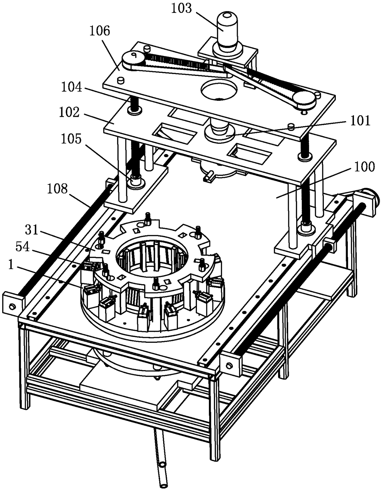
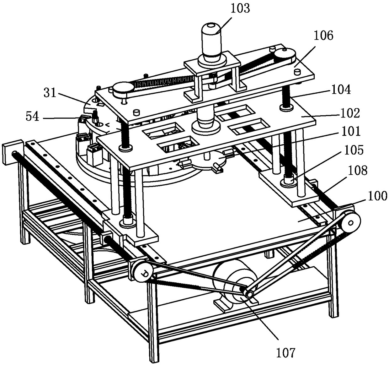
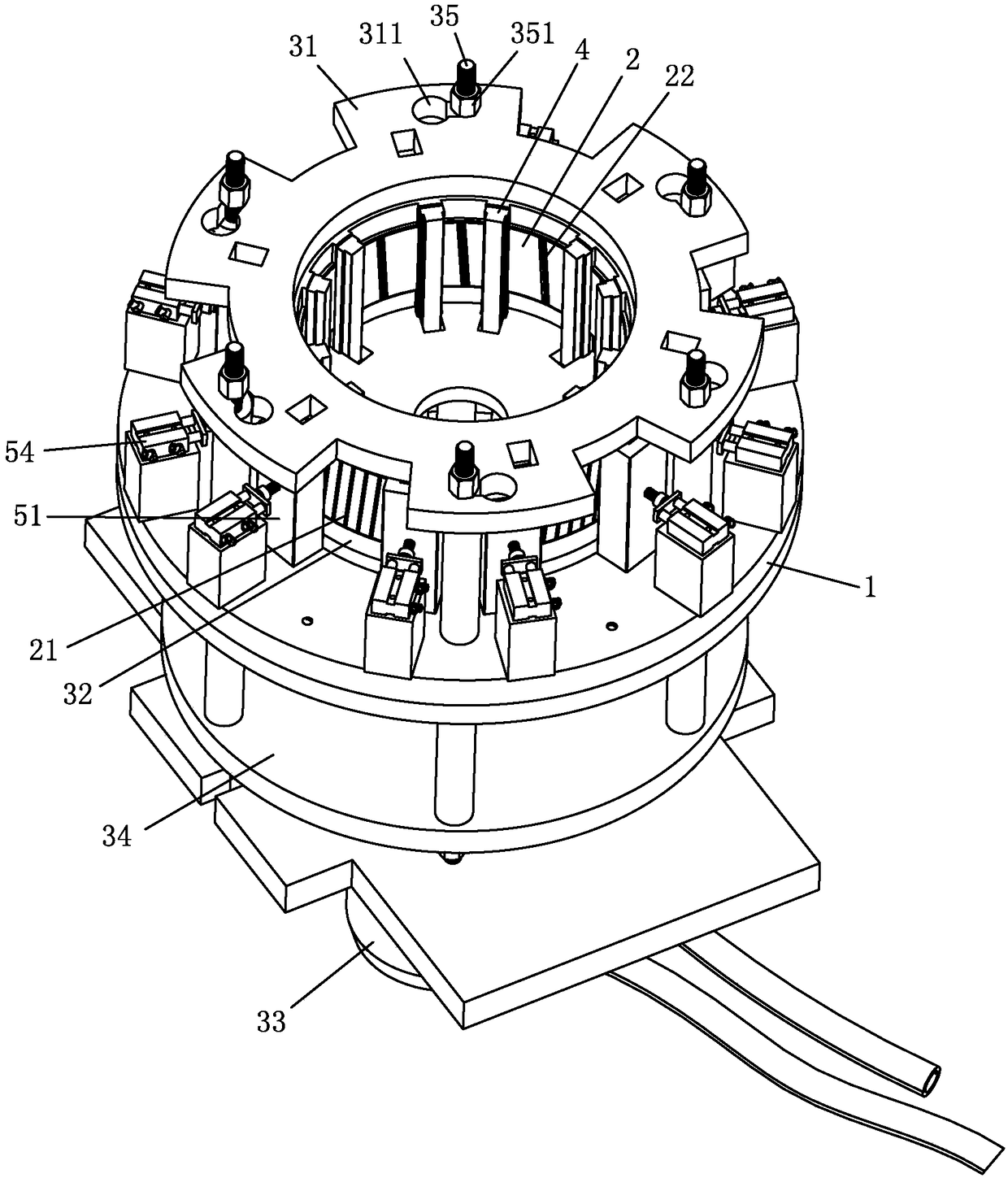
[0028] see Figure 1-Figure 6 , the internal circle automatic welding machine of the chute block type large stator, including a frame 100, the frame 100 is provided with a bearing platform 1, the top surface of the bearing platform 1 is provided with a 2. A pressing plate mechanism in which the assembled stator is tightly pressed. The top surface of the bearing table 1 is also provided with a number of inner circle positioning columns 4 that are abutted against the inner circle of the stator and inserted into the outer circular groove 21 of the stator. The outer circular groove 21 is straightly skewed by several skewing mechanisms; the frame 100 is also provided with an automatic welding mechanism 101, and the automatic welding mechanism 101 penetrates the pressing plate mechanism through the transmission mechanism and welds the inner circle of the stator 22 automatic welding.

[0029] The large stator of this embodiment is used as the stator of the elevator motor, and it is ...


PUM


Abstract

The invention relates to an automatic inner circle welding machine of a large chute splicing block type stator. The automatic inner circle welding machine of the large chute splicing block type statorcomprises a rack. The rack is provided with a bearing platform. The top face of the bearing platform is provided with a pressing plate mechanism which is used for tightly pressing the stator formed by splicing a plurality of stator splicing blocks in the pressing plate mechanism. The top face of the bearing platform is further provided with a plurality of inner circle positioning columns which abut against an inner circle of the stator and a plurality of skewing mechanisms which are inserted into an outer circle groove of the stator and used for skewing the straight outer circle groove. The rack is further provided with an automatic welding mechanism. The automatic welding mechanism penetrates into the pressing plate mechanism through a transmission mechanism and carries out automatic welding on a welded joint of the inner circle of the stator. According to the automatic inner circle welding machine of the large chute splicing block type stator, when the stator splicing blocks are spliced into the large stator, the stator splicing blocks are preinstalled in the pressing plate mechanism, then, the pressing plate mechanism is tightened, the skewing mechanisms are used for skewing the outer circle groove into a chute shape from a straight groove shape, finally, the automatic welding mechanism is used for welding the welded joint of the inner circle of the stator, and the needed large stator is quickly and stably assembled.

Description

technical field [0001] The invention relates to an automatic inner circle welding machine of a chute block type large stator. Background technique [0002] In the prior art, the stator is formed by stacking the entire stator laminations, and the large stator (such as the elevator stator) is relatively large in size, therefore, the entire stator lamination needs to be stamped with a large-sized sheet. As a result, there are a lot of waste materials, resulting in high cost. [0003] In order to reduce the cost of large stators, we have adopted a new stator structure, which is assembled by several fan-shaped stator blocks. The waste is smaller, which can effectively and greatly reduce the cutting and production costs. [0004] For the stator assembled from stator blocks, the inner circular seams need to be welded to form a stable and stable stator. However, due to the large overall volume of the large stator, the tolerance of the stator block assembly is also large. How to e...

Claims


Application Information

Patent Timeline
IPC IPC(8): B23K37/00B23K37/053B23K37/02
CPCB23K37/00B23K37/0211B23K37/0461B23K37/053
Inventor 何冠谦
Owner 佛山市力雄机电有限公司
Features
  • Generate Ideas
  • Intellectual Property
  • Life Sciences
  • Materials
  • Tech Scout
  • Unparalleled Data Quality
  • Higher Quality Content
  • 60% Fewer Hallucinations
Learn More