Hardware anti-rust treatment device

A technology for anti-rust treatment and hardware. It is used in grinding drive devices, grinding/polishing safety devices, metal processing equipment, etc. It can solve the problems of inconvenient grinding, ash removal, and inconvenient handling, and achieve convenient automatic grinding. Ash removal, good practicability and simple operation

Inactive Publication Date: 2019-03-19
温州法施顿电气有限公司
0 Cites 0 Cited by

AI-Extracted Technical Summary

Problems solved by technology

[0003] For tubular hardware fittings, in order to prevent internal rust, it is necessary to grind and remove dust on the inner wall of the tubular hardware fittings, and...

Abstract

The invention discloses a hardware anti-rust treatment device comprising a mounting cylinder. The wall of the mounting cylinder is provided with eight moving mechanisms. Each moving mechanism comprises a rolling wheel, a mounting bracket, a mounting plate, two guiding rods and two first springs, wherein the guiding rods penetrate through the wall of the mounting cylinder and are movably installedto the wall of the mounting cylinder, the same ends of the guiding rods are fixedly installed to the mounting plate, the mounting bracket is welded to the mounting plate, the rolling wheel and the mounting bracket are rotationally installed, the guiding rods are sleeved with the first springs correspondingly, and the first springs and the mounting plate are located outside the mounting cylinder. The eight moving mechanisms are arranged in groups of four, each set of moving mechanism are symmetrical, worm wheels are fixedly installed on one sides of the rolling wheels in two of the moving mechanisms in one set, and the mounting plates are rotationally provided with first rotating rods. The hardware anti-rust treatment device is reasonable in design structure, easy to operate, convenient touse, capable of conveniently automatically polish and dedust the inner wall of tubular hardware parts and good in practicability.

Application Domain

Revolution surface grinding machinesGrinding drives +1

Technology Topic

Computer engineering

Image

  • Hardware anti-rust treatment device
  • Hardware anti-rust treatment device
  • Hardware anti-rust treatment device

Examples

  • Experimental program(1)

Example Embodiment

[0016] The following will clearly and completely describe the technical solutions in the embodiments of the present invention with reference to the accompanying drawings in the embodiments of the present invention. Obviously, the described embodiments are only some, not all, embodiments of the present invention.
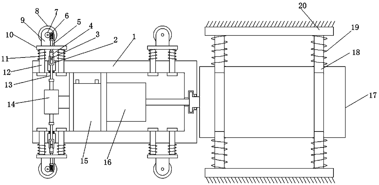
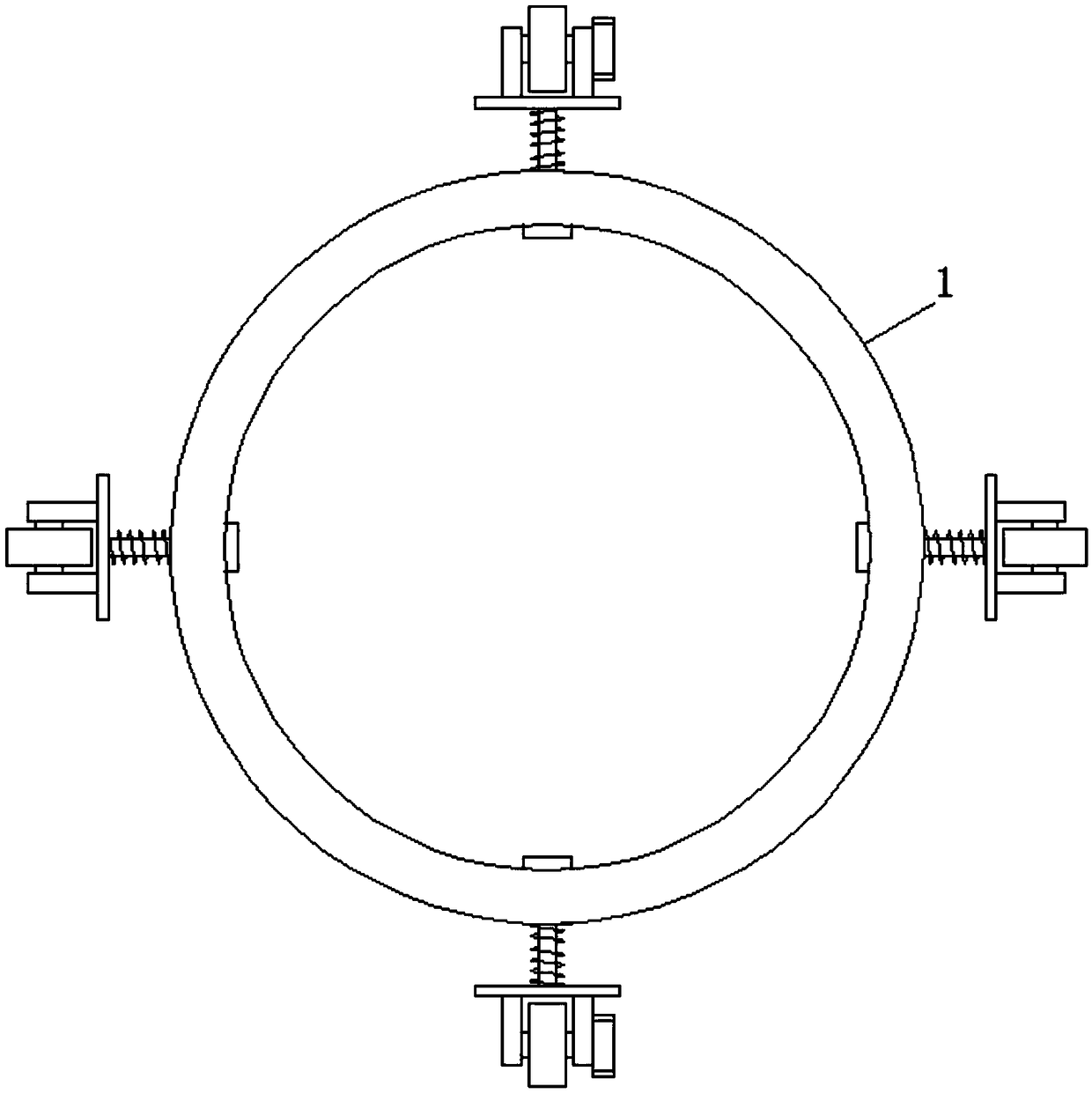
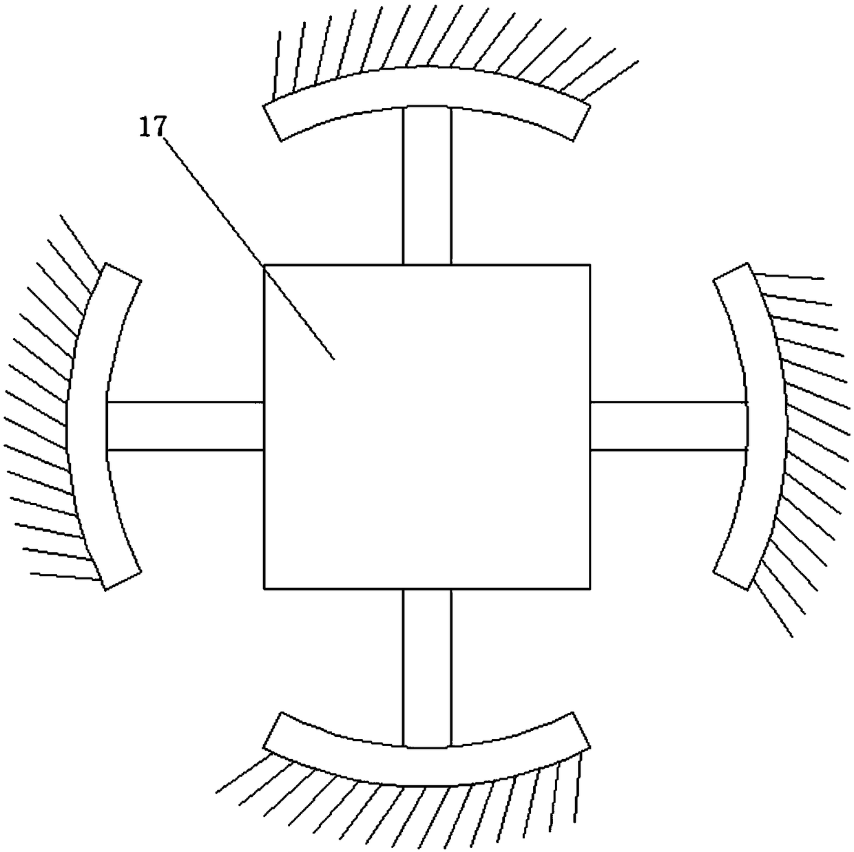
[0017] refer to Figure 1-3 , a hardware anti-rust treatment device, including a mounting cylinder 1, the wall of the mounting cylinder 1 is equipped with eight moving mechanisms, the moving mechanism includes a roller 8, a mounting frame 9, a mounting plate 10, a guide rod 12 and a first spring 11 , there are two guide rods 12 and two first springs 11, the guide rod 12 passes through the wall of the installation cylinder 1 and is movably installed with the wall of the installation cylinder 1, the same end of the guide rod 12 is fixedly installed with the installation plate 10, and the installation The frame 9 is welded with the mounting plate 10, the roller 8 and the mounting frame 9 are rotated and installed, the first springs 11 are respectively sleeved on the guide rods 12, the first spring 11 and the mounting plate 10 are located outside the mounting cylinder 1, and the eight moving mechanisms each The four constitute a group, and the moving mechanisms of each group are symmetrical to each other. One side of the rollers 8 in the two moving mechanisms in one group of moving mechanisms is fixedly installed with a worm wheel 7, and the mounting plate 10 is rotatably installed with a first rotating rod 5 A worm 6 is fixedly mounted on one end of the first rotating rod 5, and the worm 6 meshes with the worm wheel 7. The other end of the first rotating rod 5 passes through the mounting plate 10 and is fixedly installed with a U-shaped first buckle 4. The first buckle A clip 3 is welded between the two vertical walls of the button 4, a U-shaped second button 2 is arranged below the first button 4, the button 3 is located in the mouth of the second button 2, and the installation tube 1 The wall body is provided with two grooves, and the second buckles 2 are respectively located in the grooves, and one end of the second buckle 2 is welded with a second rotating rod 13, and one end of the second rotating rod 13 extends into the installation cylinder 1 , the inner wall of the installation cylinder 1 is fixedly installed with two partition plates, and one side of one of the partition plates is fixedly installed with a biaxial motor 14, and the two output shafts of the biaxial motor 14 are connected to one end of the second rotating rod 13 respectively. Fixed installation.
[0018] In this embodiment, when in use, the whole device such as figure 1 As shown in the installation, place the tubular hardware vertically, press the wiper 20 and the roller 8, and insert the device from the top of the tubular hardware into its interior, and the roller 8 contacts the inner wall of the tubular hardware under the action of the first spring 11 In close contact, the wiping plate 20 is also in close contact with the inner wall of the tubular hardware under the action of the second spring 19, and the single-axis motor 16 and the double-axis motor 14 are started, and the double-axis motor 14 drives the second rotating rod 13 to rotate, and the second rotation The rod 13 drives the second buckle 2 to rotate, and the second buckle 2 drives the first buckle 4 to rotate through the buckle 3, so that the first buckle 4 drives the first rotating rod 5, so that the worm 6 drives the worm wheel 7 to rotate, so that the roller 8 rotates, the roller 8 interacts with the inner wall of the tubular hardware, so that the device advances, and the up and down freedom of the latch 3 is not restricted, but the degree of freedom on the horizontal plane is limited by the second buckle 2, so when the latch 3 is in the adjusted position It can still drive the second buckle 2 to rotate, and the single-axis motor 16 drives the mounting block 17 to rotate, thereby driving the wiper plate 20 to polish and remove dust on the inner wall.
[0019] Also, if Figure 4 As shown, in the mounting block 17, there are air draft holes 21 arranged axially along the mounting block 17, and several small air draft holes 22 communicated with the air exhaust holes are respectively provided on the four outer planes of the mounting block 17, A screw rod 23 is arranged in the air exhaust hole and the screw rod is connected to the drive motor, and an impeller that rotates synchronously with the screw rod is provided at one end of the screw rod near the drive motor.
[0020] The above is only a preferred embodiment of the present invention, but the scope of protection of the present invention is not limited thereto, any person familiar with the technical field within the technical scope disclosed in the present invention, according to the technical solution of the present invention Any equivalent replacement or change of the inventive concepts thereof shall fall within the protection scope of the present invention.

PUM

no PUM

Description & Claims & Application Information

We can also present the details of the Description, Claims and Application information to help users get a comprehensive understanding of the technical details of the patent, such as background art, summary of invention, brief description of drawings, description of embodiments, and other original content. On the other hand, users can also determine the specific scope of protection of the technology through the list of claims; as well as understand the changes in the life cycle of the technology with the presentation of the patent timeline. Login to view more.

Similar technology patents

Roads traffic collision early warning device

ActiveCN101178846AReasonable structureGood warning effect
Owner:杭州尊鹏信息科技有限公司

Double-mould turnover casting machine for casting piston

Owner:SHIJIAZHUANG JINGANG KAIYUAN POWER SCI & TECH

Polishing device for dustless building grounds

Owner:CHANGSHA WUDAO IND DESIGN CO LTD

Classification and recommendation of technical efficacy words

Why Eureka
Try Eureka