Test method of load of tool end of robot

A test method and robot technology, applied in the field of robotics, can solve problems such as large amount of calculation, increased equipment cost, and complicated calculation process, and achieve the effects of improving measurement accuracy, saving costs, and avoiding moment of inertia

Active Publication Date: 2019-03-19
库曼机器人(武汉)有限公司
View PDF6 Cites 10 Cited by
  • Summary
  • Abstract
  • Description
  • Claims
  • Application Information

AI Technical Summary

Problems solved by technology

This method has a large amount of calculation and the calculation process is complicated
For irregular tools and workpieces, it is difficult to detect the center of gravity of the load
The moment of inertia of the load generally needs to be measured by special instruments, and the measurement process generally requires secondary clamping, which also results in inaccurate measurement and virtually increases the cost of equipment

Method used


Image

  • Test method of load of tool end of robot
  • Test method of load of tool end of robot
  • Test method of load of tool end of robot

Examples


Embodiment Construction

[0027] In order to make the purpose, technical solution and advantages of the present invention clearer, the embodiments of the present invention will be further described below in conjunction with the accompanying drawings.

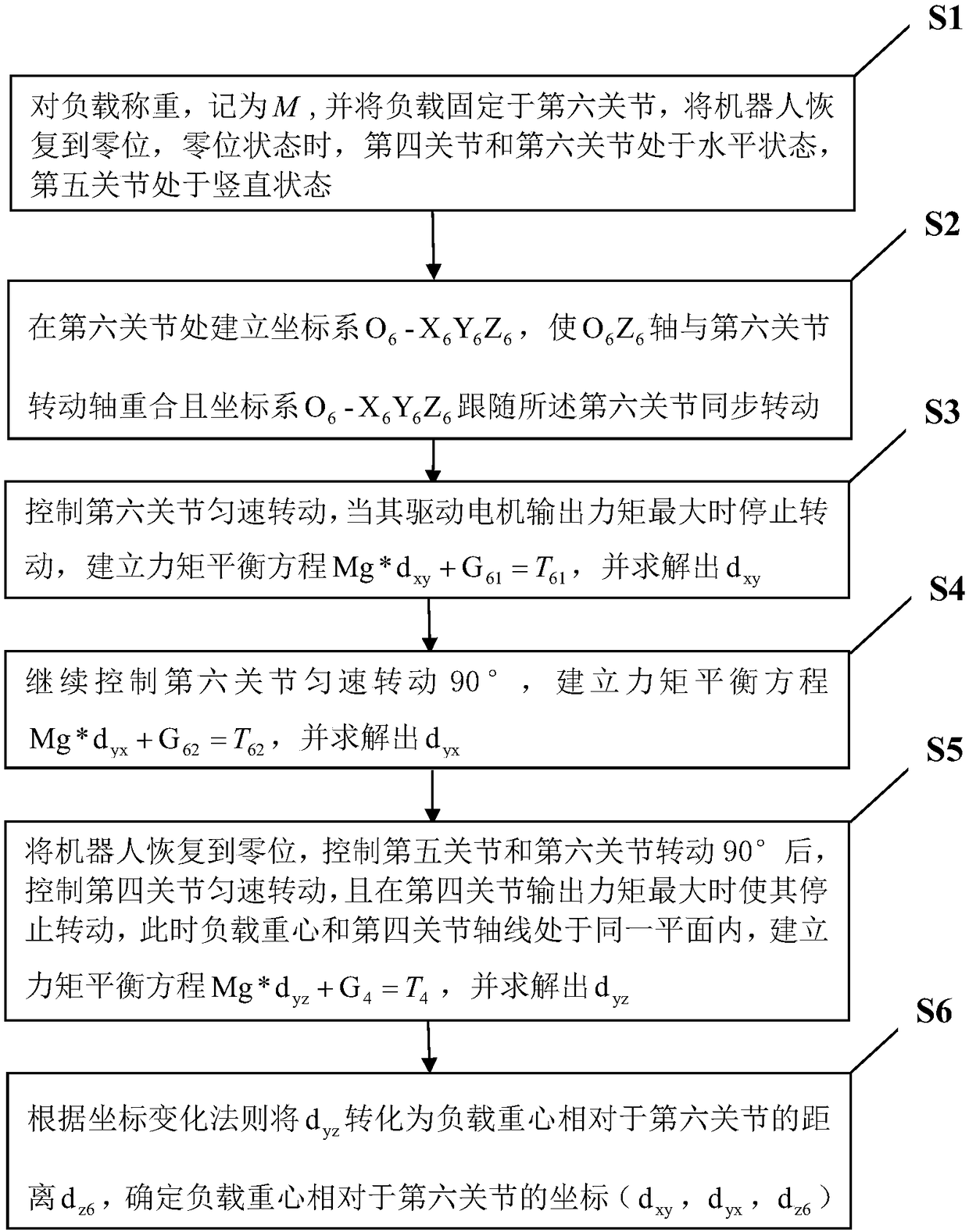
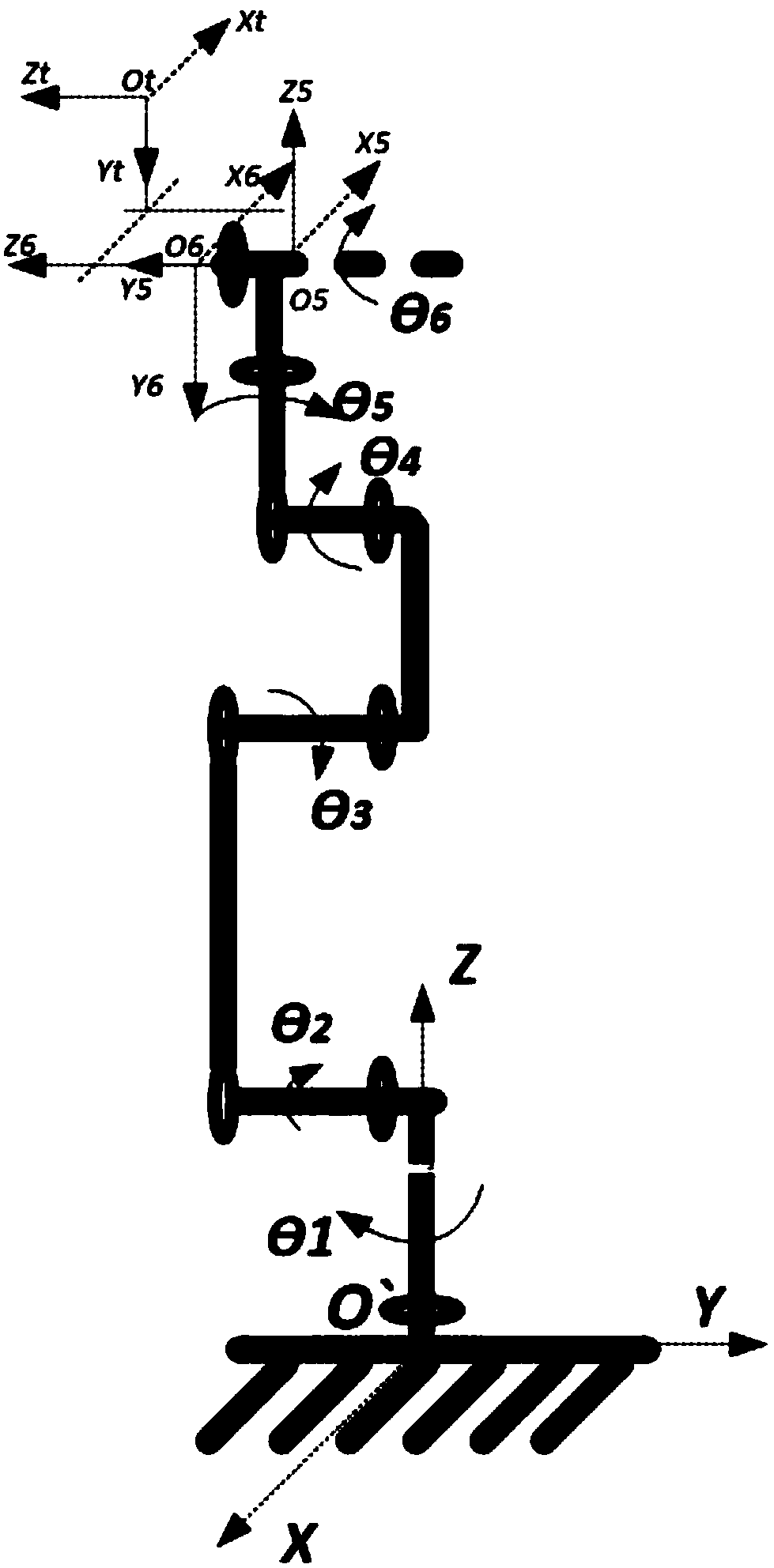
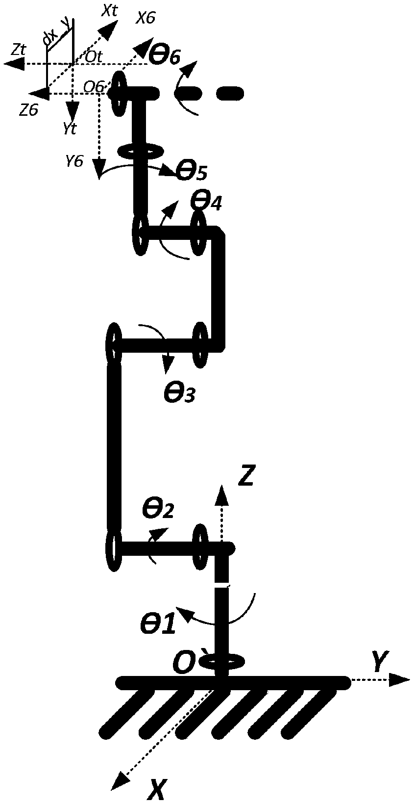
[0028] Please refer to figure 1 and figure 2 , an embodiment of the present invention provides a method for testing the load on the tool end of a robot, the robot includes six joints connected in sequence, respectively the first joint θ 1 ~6th joint θ 6 , each joint is equipped with a drive motor to drive its rotation, the first joint θ 1 Fixed vertically on the base of the fixed body, the first joint θ 1 , the second joint θ 2 , the third joint θ 3 does not rotate, the initial state of the robot is in the zero state, and in the zero state, the second joint θ 2 , the third joint θ 3 , the fourth joint θ 4 and the sixth joint θ 6 are in a horizontal state, the fifth joint θ 5 in a vertical position.

[0029] Described test method specifically ...


PUM


Abstract

The invention provides a test method of a load of a tool end of a robot. According to the test method, three joints at the tail end of the robot are controlled to rotate by a certain angle to measurethe gravity center of the load and the rotational inertia, the sixth joint is rotated to enable the axis of the sixth joint and the gravity center of the load to be located on the same plane; after the robot is stable, the maximum gravitational torque is applied to the sixth joint by the load, the motor output toque is read, and a force arm length is worked out to serve as the absolute value of the position of the load in one direction relative to the origin of coordinates of the sixth joint; and similarly, the three joints at the tail end of the robot are rotated to work out the gravity centers of the load in the other two directions; or, one or two of the joints are rotated by a certain angle, and the other joints are controlled to rotate to enable the axes of the joints and the gravitycenter of the load to be located on the same horizontal plane, so that the position of the gravity center is worked out; and on this basis, the three joints at the tail end of the robot are controlledto rotate in a uniform acceleration mode, so that the rotational inertias of the load in the three directions are worked out. The test method has the beneficial effects that the gravity center and rotational inertia of the load are accurately detected, and the test method is universal.

Description

technical field [0001] The invention relates to the technical field of robots, in particular to a method for testing the load of a robot tool end. Background technique [0002] Robots have been widely used in 3C, auto parts, metal processing, food, medicine, logistics and other industries. For each product or working condition, there are corresponding tools installed at the end of the robot. As a load and a part of the robot body, its mass, center of gravity, and moment of inertia have a great impact on the performance of the robot body, such as joint torque output. Therefore, before installing the load, it is necessary to detect its mass, relative to the position of the center of gravity of the tool end and the moment of inertia. The quality of the load can be directly obtained by weighing with an electronic scale, but the load is composed of different parts, the shape of the composition is irregular, and the mass distribution is uneven. Therefore, it is difficult to det...

Claims


Application Information

Patent Timeline
IPC IPC(8): B25J19/00
CPCB25J19/00B25J19/0095
Inventor 陈发卢小东
Owner 库曼机器人(武汉)有限公司
Why Eureka
Try Eureka