
Vehicle body and vehicle body control method

A vehicle body and controller technology, which is applied to vehicle components, layouts combined with internal combustion engine fuel supply, doors, etc. Efficiency, avoid component damage, prevent collision effect

Inactive Publication Date: 2019-03-19
SAIC GENERAL MOTORS +1
View PDF6 Cites 4 Cited by
  • Summary
  • Abstract
  • Description
  • Claims
  • Application Information

AI Technical Summary

Problems solved by technology

If the fuel door is open and the sliding door is also sliding towards the fuel door, it will cause the sliding door to collide with the fuel door, causing damage to parts
[0003] At present, in order to prevent the sliding door from colliding with the refueling door, a simple mechanical method is usually used to realize the interlocking of the sliding door and the refueling door. When the door is opened, control the wiring harness of the body to release the lock, and prevent the sliding door from sliding toward the fuel door; when the fuel door is closed, control the body wiring harness to tighten, so that the lock is closed, and the sliding door can slide toward the fuel door, the structure is complex , unable to realize electronic automation control, low work efficiency

Method used


Image

  • Vehicle body and vehicle body control method
  • Vehicle body and vehicle body control method
  • Vehicle body and vehicle body control method

Examples


Embodiment 1

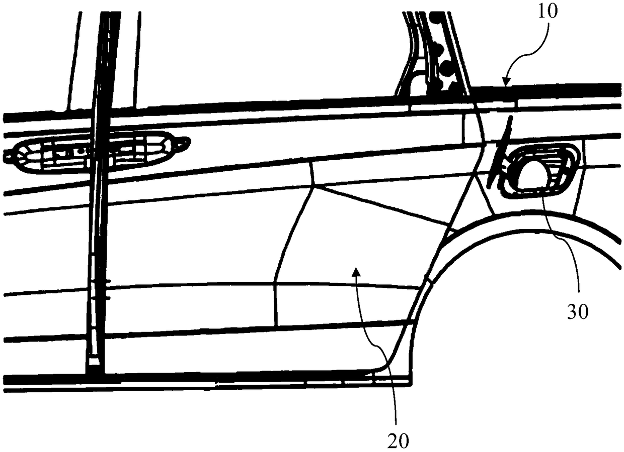
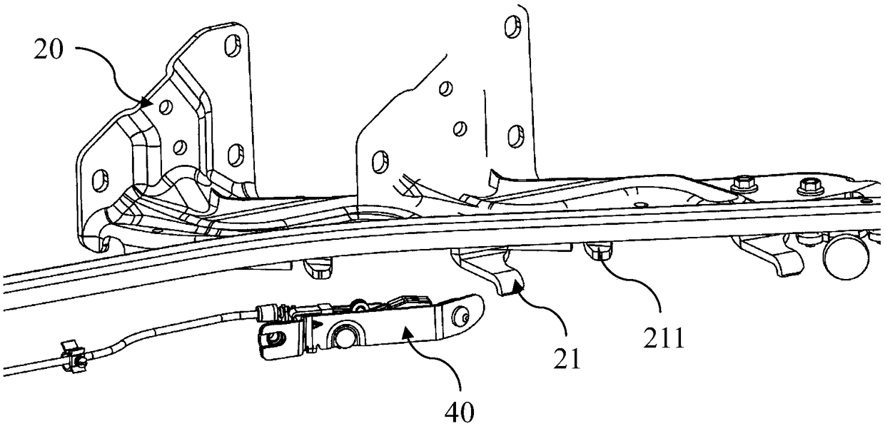
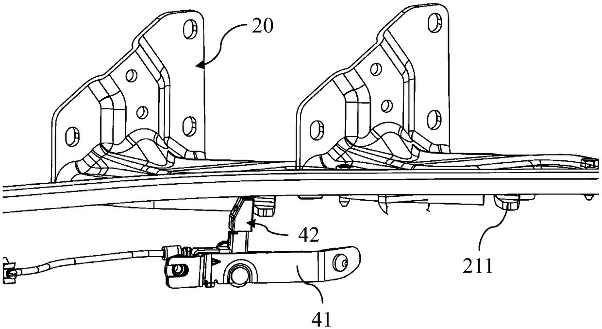
[0046] Such as Figure 1-Figure 6 As shown, a vehicle body provided by an embodiment of the present invention includes a vehicle body body 10 , a sliding door 20 that is slidably connected to the vehicle body body 10 through a bracket 21 , and a door mounted on the vehicle body body 10 . On the refueling door 30 located on the rear side of the sliding door 20, the bracket 21 includes a bracket baffle 211, and the sliding door 20 and the bracket baffle 211 can slide toward the refueling door 30 integrally, It also includes a locking mechanism 40 and a controller. The fuel door 30 is provided with a first position sensor 31, wherein:

[0047] The locking mechanism 40 has a closed position and an open position for preventing the bracket baffle 211 from sliding toward the fuel door 30 , and can be switched between the open position and the closed position;

[0048] The first position sensor 31 is used to detect the working state of the fueling door 30, and the working state of th...

Embodiment 2

[0068] Such as Figure 7 as shown, Figure 7 It is a work flow chart of a vehicle body control method provided by an embodiment of the present invention, including:

[0069] Step S11: Detect the working state of the fuel door, which includes the open state and the closed state of the fuel door;

[0070] Step S12: When the working state of the fuel door is the fuel door open state, control the locking mechanism of the vehicle body to be in the open position, the locking mechanism has a closed position and is used to block the bracket A plate slides toward an open position of the fuel door and is switchable between the open position and the closed position.

[0071] Specifically, step S11 is performed to detect the working state of the fuel pedal through the first position sensor provided on the fuel valve, and send the result to the controller. When the working state of the fuel door is the fuel door open state, step S12 is performed to control the locking mechanism to be in...

Embodiment 3

[0076] Such as Figure 8 as shown, Figure 8 It is a work flow chart of a vehicle body control method provided by an optional embodiment of the present invention, including:

[0077] Step S21: Detect the working state of the fuel door, which includes the open state and the closed state of the fuel door;

[0078] Step S22: When the working state of the fuel door is the fuel door open state, control the locking mechanism of the vehicle body to be in an open position;

[0079] Step S23: Detect the sliding door working state of the sliding door, the sliding door working state includes the sliding door open state and the sliding door closed state;

[0080] Step S24: When the working state of the sliding door is the closed state of the sliding door, controlling the locking mechanism to be in the open position.

[0081] Specifically, the second position sensor provided on the sliding door performs step S23 to detect the sliding door working state of the sliding door, and sends it ...


PUM


Abstract

The invention discloses a vehicle body and a control method thereof. The vehicle body comprises a vehicle body main body, a sliding door and an oil filling door, wherein the sliding door can be slidably connected to the vehicle body main body through a bracket; the oil filling door is arranged on the vehicle body main body and positioned at the rear side of the sliding door; the bracket comprisesa bracket baffle, the sliding door and the bracket baffle can integrally slide towards the oil filling door, and the vehicle body also comprises a locking mechanism and a controller, wherein the oil filling door is provided with a first position sensor, the locking mechanism is provided with a closed position and an open position for blocking the bracket baffle from sliding towards the oil fillingdoor, and can be switched between the open position and the closed position; a first position sensor used for detecting the working states of the oil filling door, wherein, the working states of theoil filling door comprises an open state and a closed state; a controller used for controlling the locking mechanism to be in the open position when the working state of the oil filling door is the open state. According to the invention, the working state of the oil filling door is detected by the controller, so that the sliding of the sliding door is automatically controlled.

Description

technical field [0001] The invention relates to the technical field of automobiles, in particular to a vehicle body and a control method for the vehicle body. Background technique [0002] With the advancement of technology, cars have become a means of transportation for people to travel. Automobile sliding doors are generally seen on multi-purpose vehicles (MPVs), and many commercial vehicles can also see sliding doors, such as micro-faces and light buses. The biggest advantage of the sliding door is that it has better convenience after opening, which is convenient for passengers to enter and exit the compartment and to load and unload goods in the compartment. The fuel door is usually arranged on the rear side of the sliding door. When the sliding door is opened, it slides toward the fuel door side; when the sliding door is closed, it slides toward the front of the vehicle. If the fuel door is in the open state and the sliding door slides towards the fuel door at this ti...

Claims


Application Information

Patent Timeline
IPC IPC(8): B60J5/06B60K15/05
CPCB60J5/062B60K15/05B60K2015/053B60K2015/0538B60K2015/0546
Inventor 崔蒿张长驰
Owner SAIC GENERAL MOTORS
Learn More