Small-size light guide plate conveying system

A technology of conveying system and light guide plate, applied in the field of light guide plate conveying and processing, can solve the problems of easy-to-touch products and damage, and achieve the effect of reducing labor costs, lowering defect rate, and reducing human-induced damage.

Pending Publication Date: 2019-03-19
深圳市高美福电子有限公司
View PDF0 Cites 2 Cited by
  • Summary
  • Abstract
  • Description
  • Claims
  • Application Information

AI Technical Summary

Problems solved by technology

In the traditional process, these two stations are manually conveyed. Due to the fast processing speed of the small-sized light guide plate, an average of 3-4 seconds is produced. In order to cope with the high-speed conveying, it is easy to touch and cause product damage.

Method used


Image

  • Small-size light guide plate conveying system
  • Small-size light guide plate conveying system
  • Small-size light guide plate conveying system

Examples


Embodiment 1

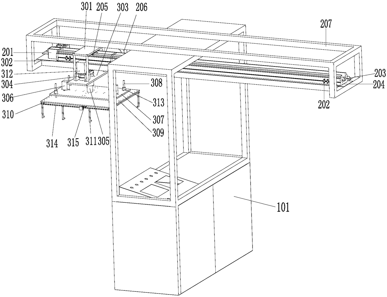
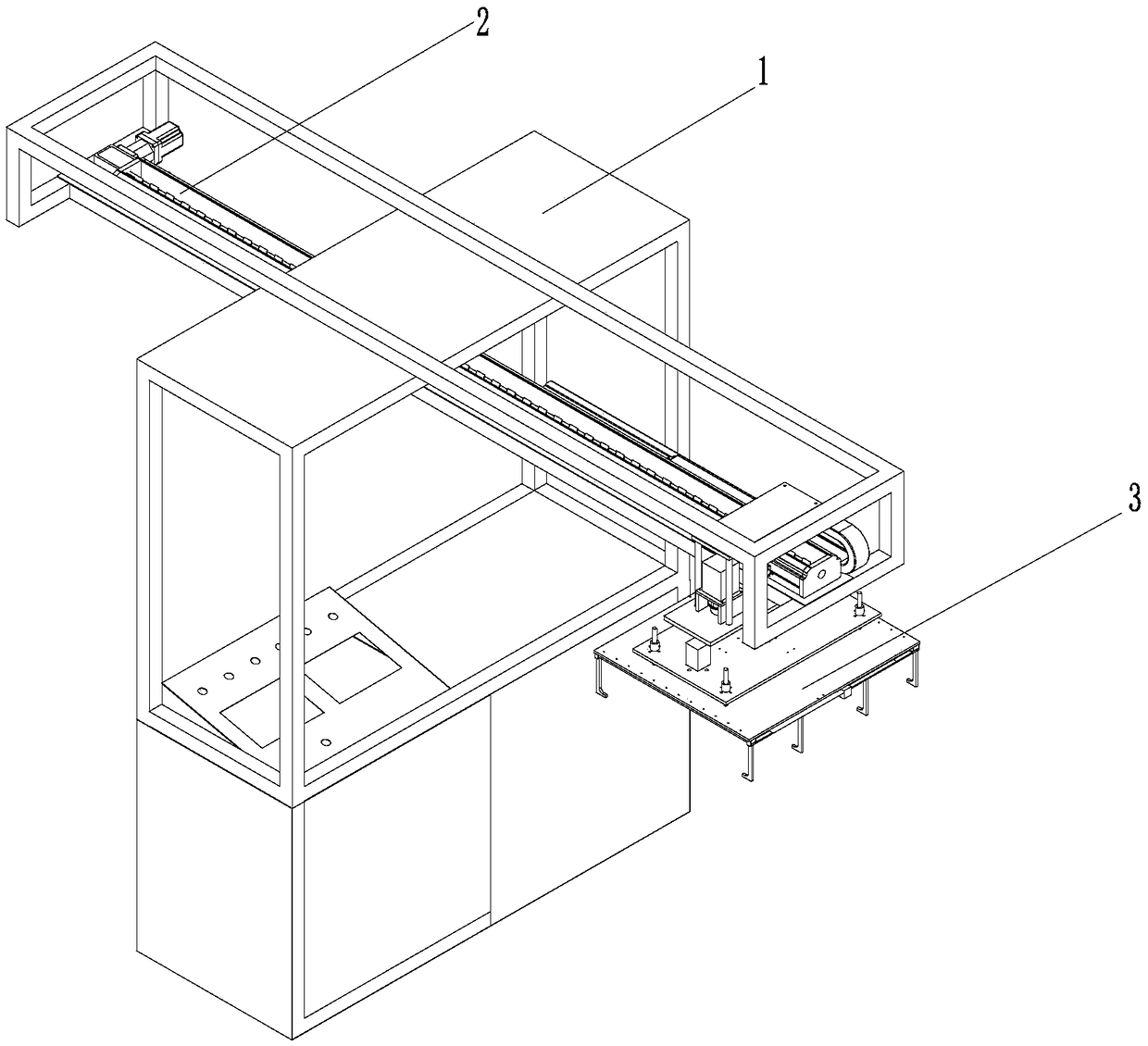
[0024] Such as Figure 1-4 As shown, a small-sized light guide plate transmission system includes a fixing mechanism 1, a screw driving mechanism 2, and a rotating clamping mechanism 3. The fixing mechanism 1 includes a first frame 101, and the screw driving mechanism 2 is installed on the fixing mechanism 1. On the first frame 101, the screw drive mechanism 2 includes a rotary motor 201, an inductor 202, a high-speed precision screw 203, a guide rail 204, a slider 205, a wire slot 206, a second frame 207, and a rotary clamping mechanism 3 Including upper fixed plate 301, fixed plate connecting column 302, support plate 303, belt 304, rotating shaft 305, cylinder 306, fixed plate 307, fixed connecting rod 308, lower fixed plate 309, movable guide rail 310, eight-claw gripper 311, The first rotary motor 312 , the fixed guide rail 313 , the movable rod 314 , the second rotary motor 315 , and the rotary clamping mechanism 3 are installed on the screw drive mechanism 2 .

Embodiment 2

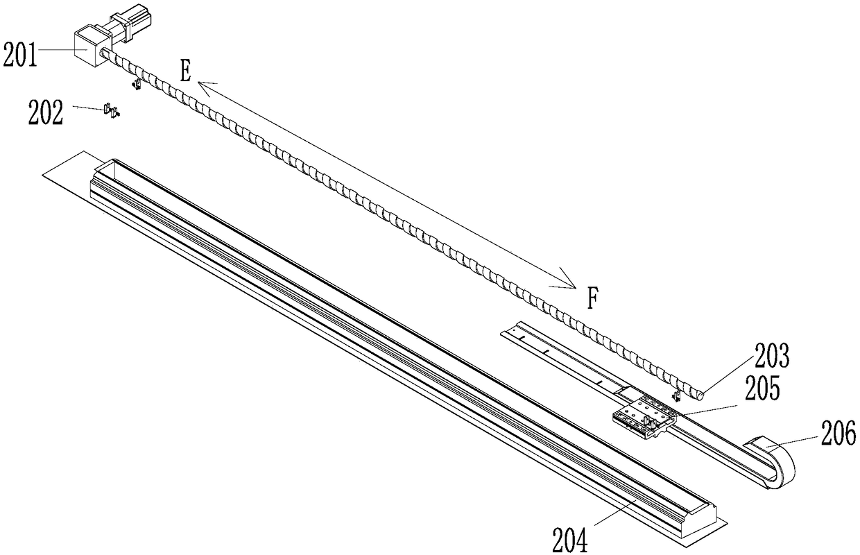
[0026] On the basis of Embodiment 1, the second frame 207 is installed on the first frame 101, the first frame 101 is used to fix the screw drive mechanism 2 and the rotary clamping mechanism 3, and the guide rail 204 is fixedly installed on the second frame. In the middle of the bottom of the inner cavity of the frame 207, the rotary motor 201 is fixedly connected to the left side of the top of the guide rail 204. The high-speed precision screw rod 203 is installed inside the guide rail 204 and connected to the output end of the rotary motor 201. The rotary motor 201 provides high-speed precision wire rods. The rotating power of the rod 203, the slider 205 is installed on the top of the guide rail 204.

Embodiment 3

[0028] On the basis of Embodiments 1 and 2, one end of the bottom of the slider 205 extends to the inside of the guide rail 204 and is threaded with the high-speed precision screw 203. The high-speed precision screw 203 is used to transmit the power of the slider 205, and the bottom of the wire groove 206 One end of the guide rail 204 is fixedly connected to the back of the top right side of the guide rail 204. The guide rail 204 supports the slider 205 and provides guidance. One end of the back of the slider 205 is fixedly connected to the wire groove 206. The number is two, and two sensors 202 are symmetrically fixedly connected to the fronts of the left and right sides of the top of the guide rail 204 , and the sensors 202 are used to control the position of the sensing slider 205 .


PUM


Abstract

The invention discloses a small-size light guide plate conveying system and relates to the technical field of light guide plate conveying and machining. The small-size light guide plate conveying system comprises a fixing mechanism, a screw rod transmission mechanism and a rotating clamping mechanism. The fixing mechanism comprises a first rack. The screw rod transmission mechanism is installed onthe first rack of the fixing mechanism. The screw rod transmission mechanism comprises a rotating motor, an inductor, a high-speed precise screw rod, a guide rail, a sliding block, a wire groove anda second rack. The rotating clamping mechanism comprises an upper fixing plate, a fixing plate connecting pillar, a supporting plate, a belt, a rotating shaft, an air cylinder, a fixing plate, a fixing connecting rod, a lower fixing plate, a movable guide rail, an eight-claw gripper, a first rotating motor, a fixed guide rail, a movable rod and a second rotating motor. By means of the small-size light guide plate conveying system, manual colliding damage is reduced, and meanwhile labor cost is reduced. By means of the light guide plate conveying system, after large-size light guide plates aremachined on a site, traditional labor conveying is omitted.

Description

technical field [0001] The invention relates to the technical field of light guide plate conveying and processing, in particular to a small-sized light guide plate conveying system. Background technique [0002] The production process of the light guide plate is mainly divided into cutting the plate, molding and polishing, pasting the side reflective strip, processing the dots, covering with a protective film, and packaging for shipment. The first three processes are mainly processed in the general workshop environment, with heavy industry maintenance capabilities. The key process is from processing dots to covering with protective film. At this time, there is no protective effect on the processing surface of the light guide plate, which is easy to cause damage, and once damaged, it cannot be repaired and will be scrapped. The processing of dots and protective film is done by machine, and the design of the machine has the function of protecting the surface of the light guid...

Claims


Application Information

Patent Timeline
Patent Type & Authority Applications(China)
IPC IPC(8): B65G49/06B65G47/90B65G43/00G02B6/00
CPCB65G49/06B65G43/00B65G47/902B65G2203/042G02B6/004G02B6/0065
Inventor 卓国雄
Owner 深圳市高美福电子有限公司
Why Eureka
Try Eureka