
Dual-way rotating lifting lug structure

A two-way rotation and lifting lug technology, applied in the field of hoisting and transportation, to achieve the effect of easy hoisting construction, easy two-way rotation and simple structure

Pending Publication Date: 2019-03-19
CHINA RAILWAY SHANGHAI ENGINEERING BUREAU GROUP CO LTD +1
View PDF0 Cites 0 Cited by
  • Summary
  • Abstract
  • Description
  • Claims
  • Application Information

AI Technical Summary

Problems solved by technology

The conventional lifting ring or lug plate structure can only rotate in one direction during the hoisting process. For large components with complex construction conditions or special spatial shapes, it often needs to be flexibly rotated in two directions to achieve the construction purpose.

Method used


Image

  • Dual-way rotating lifting lug structure
  • Dual-way rotating lifting lug structure
  • Dual-way rotating lifting lug structure

Examples


Embodiment Construction

[0047] The specific embodiments of the present invention will be described in detail below in conjunction with the accompanying drawings, so that those skilled in the art can more clearly understand how to practice the present invention. While the invention has been described in connection with preferred specific embodiments thereof, these embodiments are illustrative only and are not intended to limit the scope of the invention.

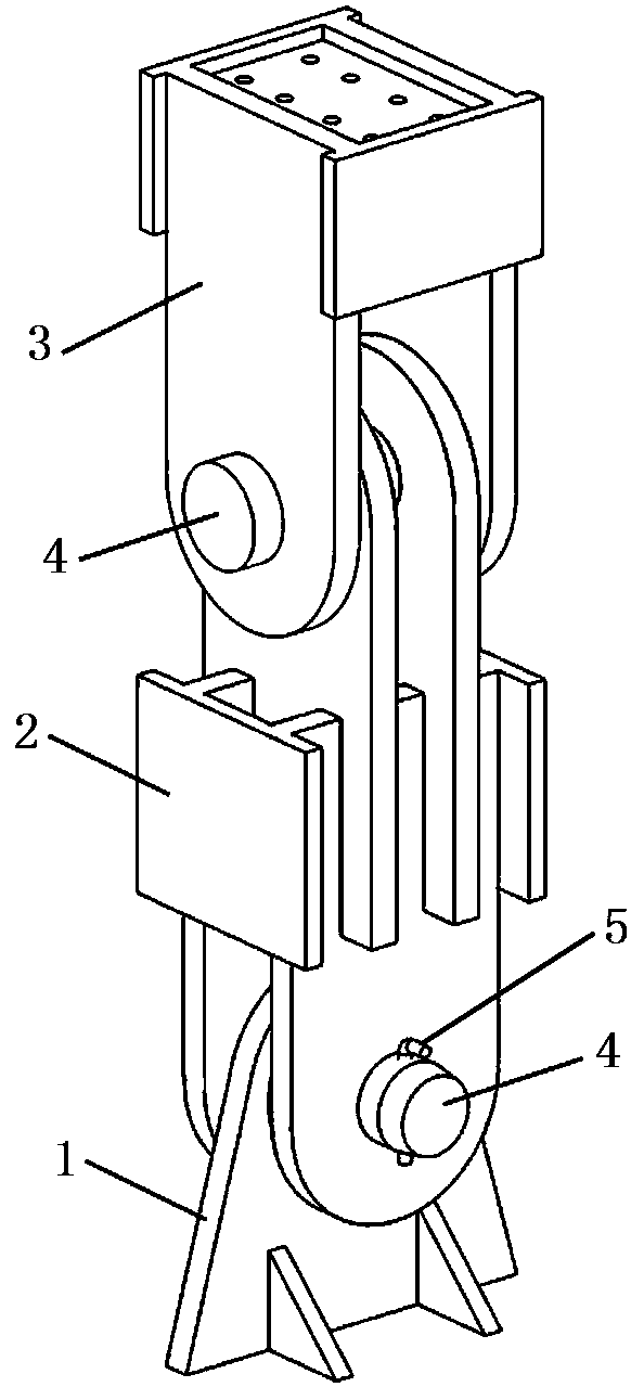
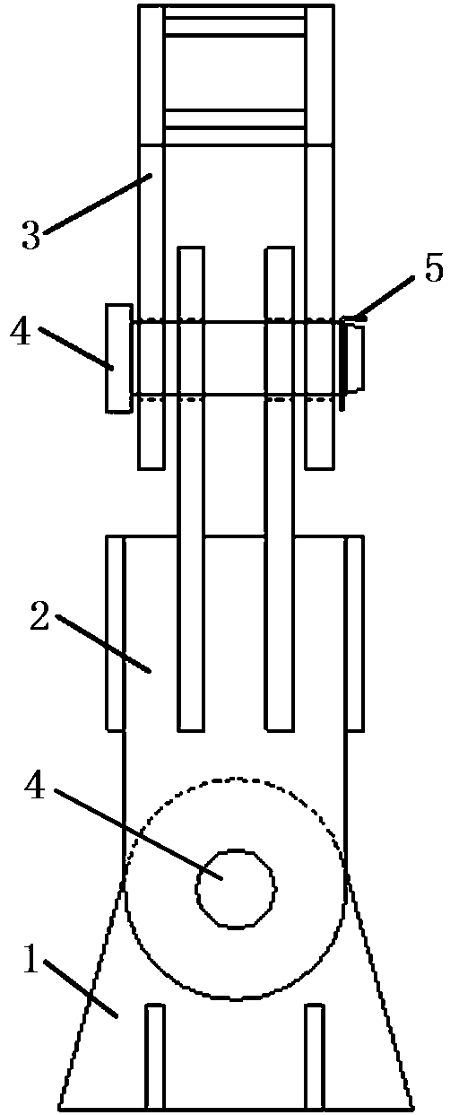
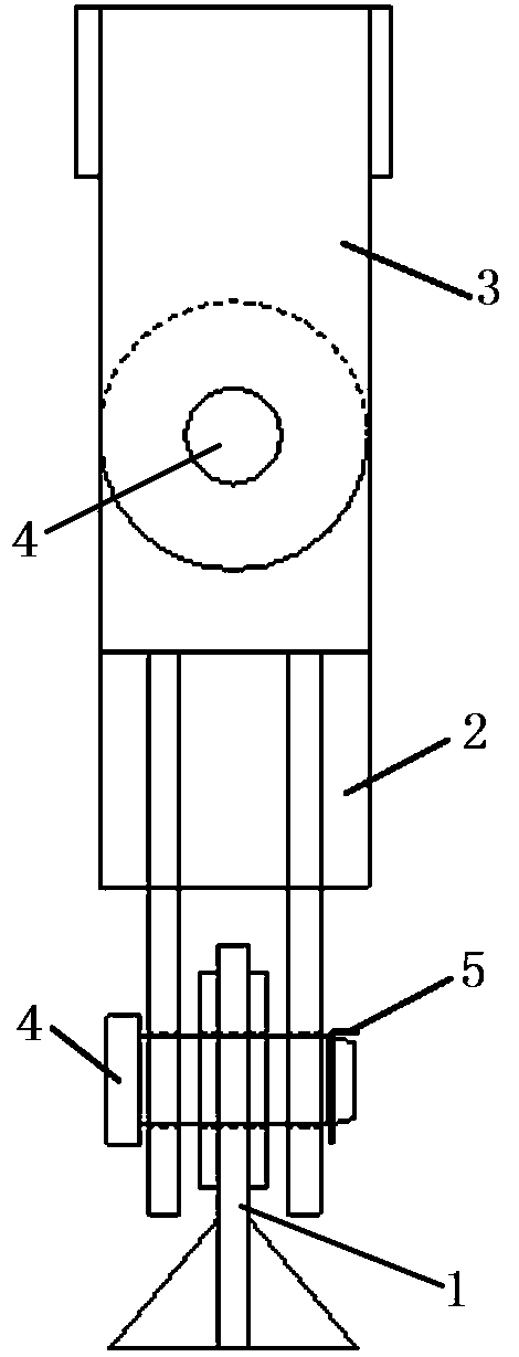
[0048] see Figure 1 to Figure 3 , a two-way rotating lifting lug structure, including lifting lug 1, connecting diverter 2 and hanging box 3 arranged in sequence from bottom to top, between the lifting lug 1 and the lower part of connecting diverter 2 and connecting the diverter 2 and the hanging box 3 are respectively hinged by a pin shaft 4, the pin tail of the pin shaft 4 is provided with a hole in the radial direction, and a safety pin 5 is inserted in the hole.

[0049] see Figure 4 to Figure 6 , the lifting lug 1 includes a lifting lug lug...


PUM


Abstract

The invention discloses a dual-way rotating lifting lug structure. The structure comprises a lifting lug, a connection turning device and a lifting box which are arranged in sequence from bottom to top, the lifting lug is hinged to the lower portion of the connection turning device through a pin shaft, the upper portion of the connection turning device and the lifting box are hinged through a pinshaft, the tail of the pin shaft is provided with a hole in the radial direction, and a safety pin is inserted in the hole; the lifting lug comprises a lifting lug plate, the connection turning devicecomprises two turning device lower lug plates and two turning device upper lug plates which are vertically in crossed connection, the lifting box comprises a lifting box lower end plate, a lifting box upper end plate and two lifting box lug plates, the lifting box lower end plate and the lifting box upper end plate are provided with corresponding anchor holes, and the upper portions of the two lifting box lug plates are connected to two sides of the lifting box lower end plate and the lifting box upper end plate. The structure is simple, dual-way rotating can be easily achieved, lifting construction is facilitated, and the structure is particularly suitable for component lifting work of complex construction conditions or particular space shapes and undefined gravity positions.

Description

technical field [0001] The invention belongs to the field of hoisting and transportation, and relates to a two-way rotating lifting lug structure. Background technique [0002] With the rapid development of my country's construction field, prefabricated structures are more and more widely used in China, especially in the professional field of steel structure. The hoisting of prefabricated components in the past generally adopts the structure of hoisting ring or lug plate, and the appropriate snap ring hoisting tool is selected for hoisting. The conventional lifting ring or lug plate structure can only rotate in one direction during the hoisting process. For large components with complex construction conditions or special spatial shapes, flexible rotation in both directions is often required to achieve the construction purpose. Contents of the invention [0003] Aiming at the above problems, the present invention provides a two-way rotating lifting lug structure. [0004]...

Claims


Application Information

Patent Timeline
Patent Type & Authority Applications(China)
IPC IPC(8): B66C1/10B66C13/08
CPCB66C1/10B66C13/08
Inventor 李国华王海峰王迎彬张鸿文孙占英李亮科
Owner CHINA RAILWAY SHANGHAI ENGINEERING BUREAU GROUP CO LTD
Learn More