Road draining structure

A drainage structure and road technology, applied in the field of road drainage, can solve the problems of not considering the drainage problem of the pavement structure layer, and achieve the effects of improving the service life, preventing dry cracks and reducing the impact force.

Inactive Publication Date: 2019-03-19
温州宏伟建设有限公司
View PDF4 Cites 7 Cited by
  • Summary
  • Abstract
  • Description
  • Claims
  • Application Information

AI Technical Summary

Problems solved by technology

In the rainy season, there is too much water, and it is inevitable that the water will enter the asphalt pavement or the interior of th

Method used


Image

  • Road draining structure
  • Road draining structure
  • Road draining structure

Examples


Embodiment Construction

[0035] The present invention will be described in further detail below in conjunction with the accompanying drawings.

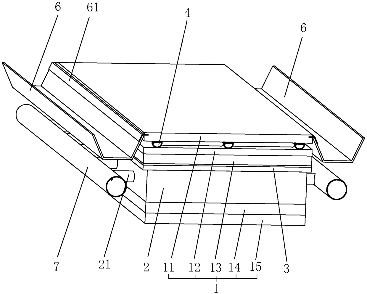
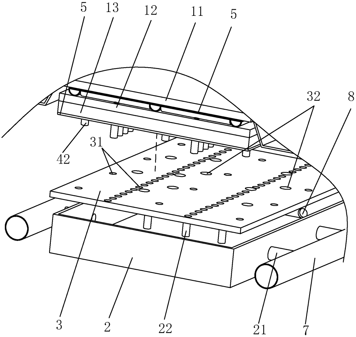
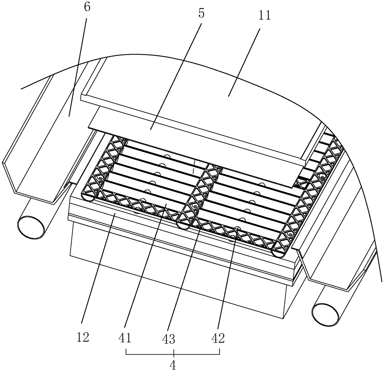
[0036] A road drainage structure such as figure 1 As shown, it includes a road body 1, a water collection chamber 2, a support plate 3, and a drainage assembly 4. The road body 1 includes a surface layer 11, a connecting layer 12, a base layer 13, a bottom layer 14, and a soil layer 15 from top to bottom. The chamber 2 is set between the base layer 13 and the bottom layer 14 , the support plate 3 is connected to the water collection chamber 2 and supports the base layer 13 , and the drainage assembly 4 is set between the surface layer 11 and the connecting layer 12 and communicated with the water collection chamber 2 . The infiltrating water on the surface layer 11 enters the drainage assembly 4, then enters the water collection chamber 2 through the drainage assembly 4, and then discharges the water in the water collection chamber 2.

[0037] combine figu...


PUM


Abstract

The invention discloses a road draining structure, belonging to the field of road draining structures. According to the technical scheme, the road draining structure is characterized by comprising a road body which sequentially comprises a surface layer, a linkage layer, a base layer, a bottom layer and a soil layer from top to bottom, wherein a plurality of water collection chambers are formed between the base layer and the bottom layer and are respectively of an opened cavity structure, support plates are fixed at the tops of the water collection chambers, cover the tops of the water collection chambers and are larger than openings of the water collection chambers; water leaking holes are formed in the support plates and are communicating with the insides of the water collection chambers; a plurality of transverse water outlet pipes communicate with the water collection chambers; and a drainage assembly for introducing water infiltrating into the surface layer into the water collection chambers is arranged between the surface layer and the linkage layer. According to the road draining structure, water infiltrating into the surface layer of the road can be well discharged.

Description

technical field [0001] The invention relates to the field of road drainage, in particular to a road drainage structure. Background technique [0002] With the continuous development of society, the road coverage rate is getting higher and higher. The road drainage structure is an important part of road construction, and the road drainage system is related to the long-term use of the road. [0003] At present, there is a relatively complete set of designs for the discharge of external water on the road. For example, a series of closed structures such as embedded curbs, masonry shoulders, and mortar retaining walls are generally designed, which better solve the problem of external water erosion. , but neglected the discharge of water inside the road surface. In the rainy season, there is too much water, and it is inevitable that it will enter the interior of the asphalt pavement or the cement concrete pavement, but the existing pavement design does not consider the drainage ...

Claims


Application Information

Patent Timeline
IPC IPC(8): E01C11/22
CPCE01C11/225E01C11/227E01C2201/20
Inventor 冯磊
Owner 温州宏伟建设有限公司
Why Eureka
Try Eureka