A debris catcher for cement slurry pouring

A technology of cement slurry and salvage, which is applied in building construction, processing of building materials, construction, etc., can solve problems such as wasting time and salvage difficulty, and achieve the effect of saving time and reducing the difficulty of salvage

Active Publication Date: 2020-10-27
浙江华港染织集团有限公司
View PDF5 Cites 0 Cited by
  • Summary
  • Abstract
  • Description
  • Claims
  • Application Information

AI Technical Summary

Problems solved by technology

[0003] In order to overcome the disadvantages that the construction workers use poles to move the sundries to the edge of the pouring pool, and then pick up the sundries by hand, so that it is difficult to salvage and waste time, the purpose of the present invention is to provide a , time-saving debris catcher for cement slurry pouring

Method used


Image

  • A debris catcher for cement slurry pouring
  • A debris catcher for cement slurry pouring
  • A debris catcher for cement slurry pouring

Examples


Embodiment 1

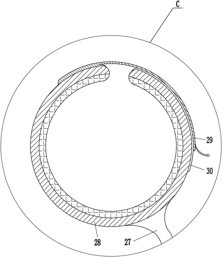
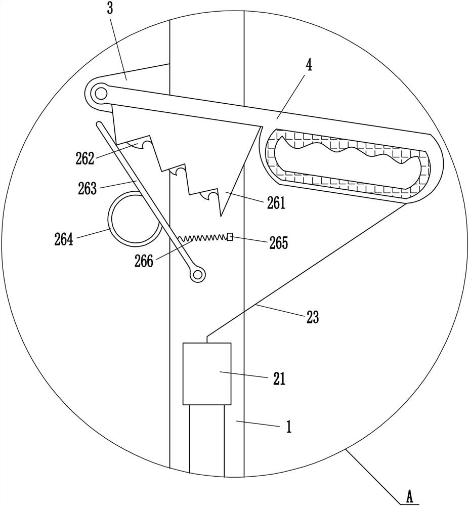
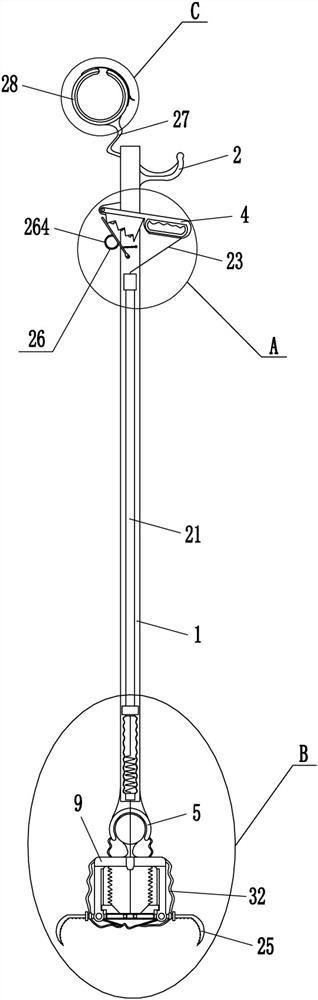
[0016] A debris catcher for cement slurry pouring, such as Figure 1-3 As shown, it includes a support rod 1, a fixed grip rod 2, a vertical plate 3, a movable grip rod 4, a semicircular frame 5, a round ball 6, a large bellows 7, a connecting block 8, a mounting plate 9, and a vertical rod 10 , slider 12, first spring 13, return-shaped frame 14, swing lever 15, roller 16, pull cord 17, guide sleeve 18, wire sleeve 19, small bellows 20, wire guide 21, second spring 22, pull wire 23. The connecting plate 24 and the clamp 25, the upper right side of the support rod 1 is fixedly connected with the fixed handle 2, the support rod 1 is connected with the fixed handle 2 by welding, and the upper left side of the support rod 1 is fixedly connected with the vertical plate 3 , the pole 1 is connected to the riser 3 by welding, the front side of the riser 3 is rotatably connected to a movable handle 4, the bottom end of the pole 1 is fixedly connected with a semicircular frame 5, and th...

Embodiment 2

[0018] A debris catcher for cement slurry pouring, such as Figure 1-3 As shown, it includes a support rod 1, a fixed grip rod 2, a vertical plate 3, a movable grip rod 4, a semicircular frame 5, a round ball 6, a large bellows 7, a connecting block 8, a mounting plate 9, and a vertical rod 10 , slider 12, first spring 13, return-shaped frame 14, swing lever 15, roller 16, pull cord 17, guide sleeve 18, wire sleeve 19, small bellows 20, wire guide 21, second spring 22, pull wire 23. The connecting plate 24 and the fixture 25, the upper right side of the support rod 1 is fixedly connected with the fixed handle 2, the upper left side of the support rod 1 is fixedly connected with the vertical plate 3, and the front side of the vertical plate 3 is connected with the movable handle 4 in a rotational manner, A semicircular frame 5 is fixedly connected to the bottom of the pole 1, a round ball 6 is arranged inside the semicircular frame 5, a large bellows 7 is fixedly connected to t...

Embodiment 3

[0021] A debris catcher for cement slurry pouring, such as Figure 1-4As shown, it includes a support rod 1, a fixed grip rod 2, a vertical plate 3, a movable grip rod 4, a semicircular frame 5, a round ball 6, a large bellows 7, a connecting block 8, a mounting plate 9, and a vertical rod 10 , slider 12, first spring 13, return-shaped frame 14, swing lever 15, roller 16, pull cord 17, guide sleeve 18, wire sleeve 19, small bellows 20, wire guide 21, second spring 22, pull wire 23. The connecting plate 24 and the fixture 25, the upper right side of the support rod 1 is fixedly connected with the fixed handle 2, the upper left side of the support rod 1 is fixedly connected with the vertical plate 3, and the front side of the vertical plate 3 is connected with the movable handle 4 in a rotational manner, A semicircular frame 5 is fixedly connected to the bottom of the pole 1, a round ball 6 is arranged inside the semicircular frame 5, a large bellows 7 is fixedly connected to th...


PUM


Abstract

The invention relates to a fisher, in particular to a sundry fisher for cement paste pouring. The sundry fisher for cement paste pouring can lower the fishing difficulty and save time. According to the technical scheme, the sundry fisher for cement paste pouring comprises a supporting rod, a fixed holding rod, a vertical plate, a movable holding rod, a semicircular frame, a round ball, a large corrugated pipe and the like; the fixed holding rod is fixedly connected to the upper portion of the right side of the supporting rod, the vertical plate is fixedly connected to the upper portion of theleft side of the supporting rod, the movable holding rod is rotationally connected to the front side of the vertical plate, the semicircular frame is fixedly connected to the bottom end of the supporting rod, and the round ball is arranged inside the semicircular frame. Sundries can be clamped through a clamp, then, the clamped sundries are moved to the portion near a pouring pool, the sundries are fished out, the fishing difficulty can be lowered, and the time can be saved; due to a blocking mechanism, the movable holding rod cannot swing downwards, and therefore the phenomenon that the clamped sundries fall down into the pouring pool due to the fact that a worker loosens the movable holding rod by accident can be avoided.

Description

technical field [0001] The invention relates to a catcher, in particular to a sundry catcher for cement slurry pouring. Background technique [0002] Construction is an artificial environment created by using the materials and technical means at hand and using certain scientific and aesthetic laws to meet social needs. When building a building, debris is often dropped into the pouring pool. In order not to affect the pouring , it is necessary to salvage the sundries in the pouring pool. Nowadays, construction workers usually use poles to move the sundries to the edge of the pouring pool, and then pick up the sundries by hand. In this way, salvaging is difficult and time-consuming, so it is necessary to A few more construction workers help salvage, which is a waste of manpower. Contents of the invention [0003] In order to overcome the disadvantages that construction workers use poles to move the sundries to the edge of the pouring pool, and then pick up the sundries by h...

Claims


Application Information

Patent Timeline
Patent Type & Authority Patents(China)
IPC IPC(8): E04G21/30
CPCE04G21/30
Inventor 詹凤程
Owner 浙江华港染织集团有限公司
Why Eureka
Try Eureka